 |
Matronics Email Lists
Web Forum Interface to the Matronics Email Lists
|
| View previous topic :: View next topic |
| Author |
Message |
terryml5c2p6(at)sympatico
Guest
|
 Posted: Wed May 14, 2008 4:09 pm Post subject: Dual redundant electrical system Posted: Wed May 14, 2008 4:09 pm Post subject: Dual redundant electrical system |
 |
|
This is my first time on the AeroElectric list server, though Ive been
lurking in the forums for some time. Im looking for comments/critiques on a
dual alternator dual battery system Ive designed. Right off the bat I have
to acknowledge the contributions made in this area by Bob Knucolls, Ive
read his book several times, and his ideas and philosophies have strongly
influenced my design. Greg Richter of Blue Mountain Avionics has also been a
major source of information and inspiration.
My application is an all-electric plane, an RV7 Im building with
Aerosance FADEC and an all-glass cockpit (AFS3400, GRT Horizon HX, and
Trutrak EFIS). Im an electrical engineer with 22 years experience in a
large electrical power utility doing protection and control work. Duplicate
redundant protection systems for ultra high reliability are the core work in
this field. In 1988 I left to start my own company, designing and
manufacturing complex expensive microprocessor-based test equipment for use
in that field. Ive flown my own Cessna 172 since 1992. Im comfortable with
electricity and flying, but Im incorporating some non-standard ideas in
this design and would appreciate comments. My prime concern is
technical/safety aspects of the electrical system, but ergonomics is
something Ive also considered important, and feel is too often neglected in
the design of complex hardware systems.
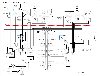
Ive attached reduced size jpg files to respect the bandwidth guidelines,
based on the original dxf files, but will verbally describe the unusual
aspects as well. I can also make available the dxf files showing clearer
detail if anyone wants them.
The first component after the battery in most aircraft systems is the master
relay, which isolates both the starter solenoid and the feed to the main
and/or essential buses. Its usually a large heavy solenoid that must be
rated to carry starter current but normally carries only a small fraction of
that current, and it takes about an amp to keep it picked up. My design uses
a 60A ANL fuse at the battery, feeding a heavy-duty automotive 70A relay in
the cockpit next to the master switch and fuse bus. I expect the smaller
lighter relay will be more reliable than a $17 solenoid, especially because
it is in a cooler lower vibration location, plus it will draw only one-tenth
of the hold-in current which means more flying time in the event of battery
only operation. In my specific system this is not insignificant, the 2 amp
draw of two master relays would be ~10% of the typical main bus load.
In a conventional system, there is no high-speed protection of the several
feet of cable that can exist from the master relay through the firewall to
the buses, other than how fast the pilot can smell smoking insulation and
turn off the switch, by which time major damage can be done to the wiring
bundle. Once I discovered ANL fuses, I saw they could offer fast automatic
protection of this major cable run. There are some good photos at
http://www.highrf.com/gallery/Power-Grids of a Legacy power grid using ANL
fuses. In my system, because I require separate FADEC buses, Ive used an
additional fuse plus relay and fuse bus mounted at the battery, to eliminate
power wiring runs into and then back out of the cockpit, which cuts weight,
simplifies wiring, and minimizes wiring exposure to damage.
A reason given for the conventional system layout is that it can isolate a
stuck starter solenoid. In my experience however, properly sized starter
solenoids are far more likely to fail open than closed, especially since
there is often an additional solenoid internal to the starter, and in worst
case its an on-ground event.
The master relays are controlled by double pole 3 position rocker switches
with internal LED annunciators (see attached Switchgear.jpg). This allows
replacement of the traditional split control switch by providing a battery
only/alternator disabled configuration in the middle position, with the
normal configuration in the upper position. Illuminated rocker switches,
apart from being more visually appealing than the typical steel toggle
switch, can provide rapid day/night visual confirmation of true operational
status since the indicator is driven by the voltage of the actual controlled
circuit. Arranging the switches in close functional groupings also makes it
easy for pre-landing checks- just brush a finger across the tops of all the
switches to verify they are in the upper position.
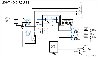
| Quote: | From there, power flows to the master bus via 60A Schottky diodes, which
generate much less heat than conventional diodes, reducing heat sink
|
requirements. There is only one main bus. I spent a lot of time trying to
decide what would go on an essential bus and what would not, plus
considering what kind of interlocks and switching would be necessary to
operate from the essential bus. In the end, given my dual batteries, dual
alternators, and better protection of the main battery feed lines, I
realized that a large essential bus is just as secure as a small one, and
not having to set up an emergency configuration during a high-stress
situation is a big advantage. Greg Richters comments about unnecessarily
complex emergency systems (page 7 of his Aircraft Wiring pdf) are spot on in
my opinion. Modern avionics and LED nav & panel lights dont draw a lot of
power, so normal daytime flight requirements are well under 20 amps for my
setup, which can be carried by the 20A backup alternator, never mind the
dual batteries. Many engine monitor systems, like the AFS3400, can monitor
alternator loading and bus voltage plus provide programmable high/low limit
alarms to these parameters, helping to keep track of loading during loss of
a power source.
I dont have an avionics master switch. I know this is controversial, and
apposed to common procedure, but here is my rationale:
1) Modern avionics are not susceptible to switching transients the way a lot
of earlier commercial gear was, especially during the early days of discrete
transistors. Additionally, though its not shown on my schematics, diode
suppression is fitted to all relays, something that wasnt usually done in
the past.
2) A single avionics master switch provides a single contingency failure
point for the avionics, after all the work to provide full redundancy.
3) Battery voltage drop during starting can cause some avionics to drop out,
but because of the dual diode isolation of the main bus, the avionics will
automatically be fed only from the normal-voltage alternate battery when the
main battery sags during start.
My fuel boost pump switch is a bit different in that there is an additional
(AUTO) position, controlled by the FADEC system. However, takeoff/landing
(MANUAL) position is up, consistent with the master switches, and as with
them LED annunciators provide additional status information.
There is no Pitot Heat control, this is a personal thing. Ive found that
after flying the same plane for a while I rarely look at airspeed, and my
setup gives me dual airspeed info plus AOA. Also, Im a VFR pilot. Doesnt
mean I wont decide to add it if I hear compelling reasons to.
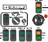
Lighting is traditionally done with a row of toggle switches, one for every
circuit, and here again I have departed from tradition, but in this case
mainly with an eye to improved ergonomics. Details are on a separate drawing
(Lights.jpg). Note that the labels on the rotary switch on the above panel
layout jpg are one revision behind the schematic. I have shown just a 2-pole
rotary switch, as high-reliability sealed switches usually have fewer
configuration choices than cheaper switches. A single rotary switch, common
in automotive applications, makes more sense to me than individual toggles.
Just turn clockwise for more lights. The first position BEACON gives nav
lights and strobes. Because strobes can be disorienting in reduced
visibility they can be disabled via the STROBE ENABLE rocker switch, but the
LED nav lights are always on given their miniscule power draw. APPROACH as
shown energizes the landing lights in a wig-wag mode for high visibility,
though this wouldnt appeal to everyone. TAXI and LANDING are the last two
positions respectively. Taxi lights are on in both positions, but one
rotation counterclockwise on the ground eliminates the long-range landing
light to avoid glare to other pilots. The small rotary knob beside the
larger lighting switch controls dimming of cockpit lights. The STROBE ENABLE
rocker switch status LED gives instant visual confirmation of strobe status,
and the tight group of 3 controls in their separate location can be operated
by touch only, like the master and fuel boost controls. This is difficult to
accomplish in the traditional row of identical toggle switches which are
often mixed in with other identical toggle controls.
I dont have panel controls for trim or flaps, these are provided on the
pilot and copilot control stick handles. A junction box is provided as a
convenient local plug-in terminus for the control stick switches, trim &
flap servos and controller, radio control lines, and power/ground lines. I
have a schematic of this if anyone wants to see it.
My instrument panel will obviously have a lot fewer controls on it than is
now common. I know that banks of toggle switches look impressive to the
uninitiated, but realistically this doesnt contribute to safety by reducing
the pilots workload. Colour coding and grouping can help a little bit, but
it still leaves something to be desired for night operations and status
checks by touch while keeping focused outside the cockpit.
Thats about it for the design highlights. One thing not evident but also
important is, wherever possible, separate physical routing of the main and
alternate system wiring, including firewall penetrations. Ive tried to
envision how the system would handle a variety of failures and havent come
up yet with any realistic scenario that would bring the plane down before
you could get to a reasonable destination point. My only minor concern at
this point is how load sharing is controlled, since the secondary alternator
is just 20A. Ive talked to Bill Bainbridge at B&C, and he said that he sets
the voltage regulator about a volt lower on the alternate. This seems like a
lot to me, Im not sure what effect this has on keeping the alternate
battery in optimum condition. I couldnt find much in Bobs book or the
forums on this point.
Anyway, Im completely open to suggestions and/or criticism. Ego should
never get in the way of safety. Id appreciate anything in the way of
comment. Im now at the point of being almost ready to start wiring things
up, and need a reality check that what I intend to do makes sense.
Thanks, Terry McMillan
| | - The Matronics AeroElectric-List Email Forum - | | | Use the List Feature Navigator to browse the many List utilities available such as the Email Subscriptions page, Archive Search & Download, 7-Day Browse, Chat, FAQ, Photoshare, and much more:
http://www.matronics.com/Navigator?AeroElectric-List |
|
| Description: |
|
| Filesize: |
112.68 KB |
| Viewed: |
427 Time(s) |
|
| Description: |
|
| Filesize: |
67.56 KB |
| Viewed: |
429 Time(s) |
|
| Description: |
|
| Filesize: |
63.39 KB |
| Viewed: |
441 Time(s) |
|
|
|
| Back to top |
|
 |
nuckolls.bob(at)cox.net
Guest
|
| Posted: Thu May 15, 2008 4:58 am Post subject: Dual redundant electrical system |
|
|
At 08:05 PM 5/14/2008 -0400, you wrote:
| Quote: | X-MIME-Autoconverted: from 8bit to quoted-printable by matronics.com id
m4F09XD3009485
Content-Type: text/plain; x-avg-checked=avg-ok-7F1173FE; format=flowed
|
<snip>
| Quote: | I've attached reduced size jpg files to respect the bandwidth guidelines,
based on the original dxf files, but will verbally describe the unusual
aspects as well. I can also make available the dxf files showing clearer
detail if anyone wants them.
|
Can you .pdf the .dxf drawings from your CAD application?
The .jpg files are kind of "swiss-cheesy" difficult to
deduce the details of your design. I'll .pdf them and repost.
| Quote: | The first component after the battery in most aircraft systems is the
master relay, which isolates both the starter solenoid and the feed to the
main and/or essential buses. It's usually a large heavy solenoid that must
be rated to carry starter current but normally carries only a small
fraction of that current, and it takes about an amp to keep it picked up.
My design uses a 60A ANL fuse at the battery, feeding a heavy-duty
automotive 70A relay in the cockpit next to the master switch and fuse
bus. I expect the smaller lighter relay will be more reliable than a $17
solenoid, especially because it is in a cooler lower vibration location,
plus it will draw only one-tenth of the hold-in current which means more
flying time in the event of battery only operation. In my specific system
this is not insignificant, the 2 amp draw of two master relays would be
~10% of the typical main bus load.
|
<snip>
Terry, you've obviously spent a great deal of time and thought
on this. At first blush, the system you propose is a relative
of Figure Z-14 as published at:
http://www.aeroelectric.com/PPS/Adobe_Architecture_Pdfs/Z14L_1.pdf
http://www.aeroelectric.com/PPS/Adobe_Architecture_Pdfs/Z14L_2.pdf
This dual-alternator/dual-battery architecture was crafted over
a period of 15 or so years and embodies practices well demonstrated
in aircraft for over 60 years.
| Quote: | Anyway, I'm completely open to suggestions and/or criticism. Ego should
never get in the way of safety. I'd appreciate anything in the way of
comment. I'm now at the point of being almost ready to start wiring things
up, and need a reality check that what I intend to do makes sense.
|
What you've proposed will probably function as you envision it.
It's more complex than the Z-14 drawings in many respects
and may not meet design goals for aircraft systems design
where we strive for low parts count and failure tolerance.
This translates directly to reductions in weight, cost, and
pilot workload. This approach also increases reliability . . .
a part that isn't there cannot be a failure item in your finished
system.
You've cited rationale for features of your proposed
system that are not a concern for most folks in aviation. It
would be a much more direct path to "architectural nirvana"
to build on what's gone before than to stir a bunch of
parts into a totally new recipe.
At the risk of sounding like I'm suffering a "not invented
here" moment, could you take a bit of time and tell us where
you perceive that Z-14 does not meet personal design goals?
Bob . . .
| | - The Matronics AeroElectric-List Email Forum - | | | Use the List Feature Navigator to browse the many List utilities available such as the Email Subscriptions page, Archive Search & Download, 7-Day Browse, Chat, FAQ, Photoshare, and much more:
http://www.matronics.com/Navigator?AeroElectric-List |
|
|
|
| Back to top |
|
|
rjquillin
Joined: 13 May 2007
Posts: 123
Location: KSEE
|
| Posted: Fri May 16, 2008 4:25 pm Post subject: Dual redundant electrical system |
|
|
On Fri, May 16, 2008 at 8:51 AM, Robert L. Nuckolls, III
<nuckolls.bob(at)cox.net> wrote:
| Quote: |
<nuckolls.bob(at)cox.net>
At 11:27 PM 5/15/2008 -0400, you wrote:
|
| Quote: |
The .pdf files are fine. I've posted them to my
server at:
http://www.aeroelectric.com/_temp/
I'll invite folks on the List to go get them and
participate in this thread as the spirit moves them . . .
|
Incomplete or incorrect url Bob?
Ron Q.
| | - The Matronics AeroElectric-List Email Forum - | | | Use the List Feature Navigator to browse the many List utilities available such as the Email Subscriptions page, Archive Search & Download, 7-Day Browse, Chat, FAQ, Photoshare, and much more:
http://www.matronics.com/Navigator?AeroElectric-List |
|
|
|
| Back to top |
|
|
rshannon
Joined: 05 Sep 2007
Posts: 62
|
| Posted: Fri May 16, 2008 5:01 pm Post subject: Dual redundant electrical system |
|
|
| Quote: |
> http://www.aeroelectric.com/_temp/
>
> I'll invite folks on the List to go get them and
> participate in this thread as the spirit moves them . . .
>
Incomplete or incorrect url Bob?
Ron Q.
|
The link works from here. Note there is an underscore character preceding "temp".
FWIW, as a former IT geek, I discouraged webmasters from using underscores in web URL's because when the whole link is automatically highlighted and the whole link becomes underscored (as it does in most email programs) the unaware reader may not realize there's a separate underscore character. If spacing is necessary, hyphens are better. Of course, spaces never work in a URL.
Ron
[quote][b]
| | - The Matronics AeroElectric-List Email Forum - | | | Use the List Feature Navigator to browse the many List utilities available such as the Email Subscriptions page, Archive Search & Download, 7-Day Browse, Chat, FAQ, Photoshare, and much more:
http://www.matronics.com/Navigator?AeroElectric-List |
|
|
|
| Back to top |
|
|
rjquillin
Joined: 13 May 2007
Posts: 123
Location: KSEE
|
| Posted: Fri May 16, 2008 5:23 pm Post subject: Dual redundant electrical system |
|
|
About 10-15 minutes after the post, it also worked for me...
Sigh.
Also paid to be an IT geek at work.
Ron Q.
At 17:57 5/16/2008, you wrote:
[quote] > http://www.aeroelectric.com/_temp/
>
> I'll invite folks on the List to go get them and
> participate in this thread as the spirit moves them . . .
>
Incomplete or incorrect url Bob?
Ron Q.
The link works from here. Note there is an underscore character preceding "temp".
FWIW, as a former IT geek, I discouraged webmasters from using underscores in web URL's because when the whole link is automatically highlighted and the whole link becomes underscored (as it does in most email programs) the unaware reader may not realize there's a separate underscore character. If spacing is necessary, hyphens are better. Of course, spaces never work in a URL.
Ron
[b]
| | - The Matronics AeroElectric-List Email Forum - | | | Use the List Feature Navigator to browse the many List utilities available such as the Email Subscriptions page, Archive Search & Download, 7-Day Browse, Chat, FAQ, Photoshare, and much more:
http://www.matronics.com/Navigator?AeroElectric-List |
|
|
|
| Back to top |
|
|
Bob McC
Joined: 09 Jan 2006
Posts: 258
Location: Toronto, ON
|
| Posted: Fri May 16, 2008 5:27 pm Post subject: Dual redundant electrical system |
|
|
The link worked fine for me and there were two .pdf's there which both

opened fine as well. One labelled "lights" the other "master". Just clicked

on the e-mail link and away we went.


Bob McC


DO NOT ARCHIVE


---
| | - The Matronics AeroElectric-List Email Forum - | | | Use the List Feature Navigator to browse the many List utilities available such as the Email Subscriptions page, Archive Search & Download, 7-Day Browse, Chat, FAQ, Photoshare, and much more:
http://www.matronics.com/Navigator?AeroElectric-List |
|
_________________
Bob McC
Falco #908
(just starting) |
|
| Back to top |
|
|
nuckolls.bob(at)cox.net
Guest
|
| Posted: Fri May 16, 2008 6:30 pm Post subject: Dual redundant electrical system |
|
|
At 05:21 PM 5/16/2008 -0700, you wrote:
| Quote: |
On Fri, May 16, 2008 at 8:51 AM, Robert L. Nuckolls, III
<nuckolls.bob(at)cox.net> wrote:
>
> <nuckolls.bob(at)cox.net>
>
> At 11:27 PM 5/15/2008 -0400, you wrote:
>
> The .pdf files are fine. I've posted them to my
> server at:
>
> http://www.aeroelectric.com/_temp/
>
> I'll invite folks on the List to go get them and
> participate in this thread as the spirit moves them . . .
>
Incomplete or incorrect url Bob?
|
Don't think so. This is a link to a directory where
you will find two separate .pdf files each of which
needs to be downloaded independently.
This is not unlike the general files archives
on my server like:
http://www.aeroelectric.com/Pictures/
and
http://www.aeroelectric.com/Reference_Docs/
where you don't get a particular document
but a directory structure for many documents.
You should be able to double-click the link
cited and it should take you to the appropriate
directory(ies).
Bob . . .
----------------------------------------)
( . . . a long habit of not thinking )
( a thing wrong, gives it a superficial )
( appearance of being right . . . )
( )
( -Thomas Paine 1776- )
----------------------------------------
| | - The Matronics AeroElectric-List Email Forum - | | | Use the List Feature Navigator to browse the many List utilities available such as the Email Subscriptions page, Archive Search & Download, 7-Day Browse, Chat, FAQ, Photoshare, and much more:
http://www.matronics.com/Navigator?AeroElectric-List |
|
|
|
| Back to top |
|
|
|
|
You cannot post new topics in this forum
You cannot reply to topics in this forum
You cannot edit your posts in this forum
You cannot delete your posts in this forum
You cannot vote in polls in this forum
You cannot attach files in this forum
You can download files in this forum
|
Powered by phpBB © 2001, 2005 phpBB Group
|

