 |
Matronics Email Lists
Web Forum Interface to the Matronics Email Lists
|
| View previous topic :: View next topic |
| Author |
Message |
nuckolls.bob(at)aeroelect
Guest
|
 Posted: Mon Feb 16, 2015 3:28 pm Post subject: Risks associated with unproven crimp tools . . . Posted: Mon Feb 16, 2015 3:28 pm Post subject: Risks associated with unproven crimp tools . . . |
 |
|
A few days ago I received some wire segments off of
an airplane that experienced burned p-lead shields,
melted insulation around center conductors AND even
failure of toggle switch.
The problem manifested in the airplane when the toggle
switch(es) failed open after 100+ hours of service.
Only after second failures of switches did more detailed
examination reveal melted insulation over outer jacket
of p-lead shields as well as melted insulation around
center conductor.
This had the 'smell' of a sneak-path ground consisting
of (1) a poor architecture of the p-lead wiring and
(2) high resistance in the starter current ground
path.
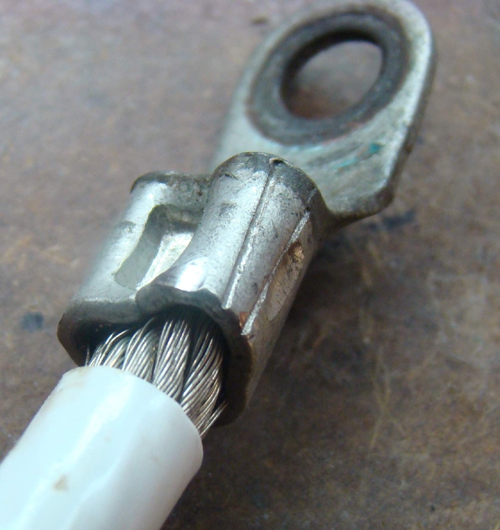
The jumper between forest of tabs ground on fire wall
hand been fabricated with a less than ideal crimp
tool.
[img]cid:.0[/img]
I did some voltage drop tests across the crimp joints and
found pretty high . . . about 2.5 millivolts at only 10 amps!
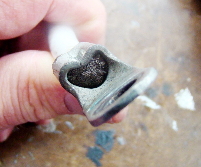
[img]cid:.1[/img]
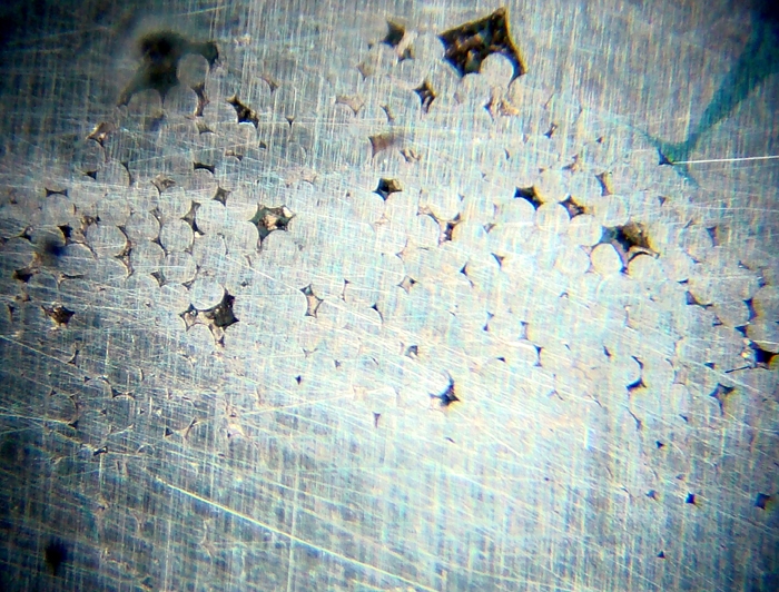
Cross-sectioned crimp joints examined under the microscope
showed numerous areas of 'failure to achieve gas tight' across
the face of the cut.
[img]cid:.2[/img]
My findings suggest some value in replacement of all terminals
applied with this tooling. I am also concerned with the corrosion
ring around the hole in the terminal . . . this should at worst
be slightly darkened tin plating. The degree of corrosion and
pitting of the mating surface suggests that this terminal was
not made-up with sufficient force to achieve gas-tightness
in the joint.
If you don't have access to a hydraulic tool and proven die
to install a terminal, then consider soldering your terminals
on per the article at:
http://tinyurl.com/qh4k7ko
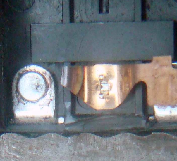
Interestingly enough, it was failure of magneto p-lead switches
that brought the deficiency to light.
[img]cid:.3[/img]
As you can see above, the phosphor bronze rocker strut that held
the moving contact was burned in two. The fixed contact is in great
shape but structure that supported the moving contact fused.
The moving contact was free to rattle around inside the switch.
If you use welding cable for your fat-wires, the weld shop
where you bought the wire can probably sell you terminals and
install them with proven tools.
Finally, make sure all mating surfaces for bolted up
joints are clean, smooth and torqued down right smartly
on assembly. This is an excellent example of a case where
marginal joint(s) took perhaps years before degrading to
the point where smoke and/or failure to perform manifested.
Bob . . .
| | - The Matronics AeroElectric-List Email Forum - | | | Use the List Feature Navigator to browse the many List utilities available such as the Email Subscriptions page, Archive Search & Download, 7-Day Browse, Chat, FAQ, Photoshare, and much more:
http://www.matronics.com/Navigator?AeroElectric-List |
|
| Description: |
|
| Filesize: |
306.64 KB |
| Viewed: |
3057 Time(s) |
|
| Description: |
|
| Filesize: |
248.54 KB |
| Viewed: |
3057 Time(s) |
|
| Description: |
|
| Filesize: |
404.05 KB |
| Viewed: |
3057 Time(s) |
|
| Description: |
|
| Filesize: |
206.12 KB |
| Viewed: |
3057 Time(s) |
|
|
|
| Back to top |
|
 |
fly4grins(at)gmail.com
Guest
|
| Posted: Tue Feb 17, 2015 8:06 am Post subject: Risks associated with unproven crimp tools . . . |
|
|
I was going down that very path, but the fellow at the rather large welding supply house told me it would take $10 per terminal to do the crimps, or for $10 I could by my own tool.  This particular widget can be bolted to a bench or held in a substantial vise and then operated with an appropriately calibrated Inertial Motivator, in this case a 2 1/2 pound sledge.  Works like a charm.  I did solder the ring end of the crimps, both to definitively seal and electrically bond the joint.  The cable end of the crimp is treated with liquid electrical tape and heat shrink tubing.  One caution:  If there is to be a bend in the cable close to the terminal, approximate the bend prior to setting the crimp.  The final product will be much easier to use.

[quote]

 ***SNIP***

 If you use welding cable for your fat-wires, the weld shop

 where you bought the wire can probably sell you terminals and

 install them with proven tools.

 ***SNIP***


[b]
| | - The Matronics AeroElectric-List Email Forum - | | | Use the List Feature Navigator to browse the many List utilities available such as the Email Subscriptions page, Archive Search & Download, 7-Day Browse, Chat, FAQ, Photoshare, and much more:
http://www.matronics.com/Navigator?AeroElectric-List |
|
|
|
| Back to top |
|
|
racerjerry
Joined: 15 Dec 2009
Posts: 202
Location: Deer Park, NY
|
| Posted: Wed Apr 15, 2015 4:05 am Post subject: Re: Risks associated with unproven crimp tools . . . |
|
|
In this and in similar threads, Bob N. has provided excellent instructions on how to achieve gas tightness with wire terminals, but I would like to add some additional info.


Some types of crimp tools press a single indentation into the barrel of the wire terminal.  This may not be ideal, but generally will suffice; however there is one mistake very commonly made with this type of tool.  Most inexpensive wire terminals are formed from flat material and have butted ends at the barrel (wire insertion point).  If the crimp tool applies an indentation over the barrel butted ends as in the photos, a poor termination is almost guaranteed.


If it is late evening and the only crimp tool that you have in your toolbox presses a single indentation into the wire terminal, take a close look at the terminal barrel to see if there is a seam (butted ends).  If there is a seam, apply the indentation on the opposite side - not across the seam as in the illustration..., or use better quality wire terminals formed from tubing without butted ends.
| | - The Matronics AeroElectric-List Email Forum - | | | Use the List Feature Navigator to browse the many List utilities available such as the Email Subscriptions page, Archive Search & Download, 7-Day Browse, Chat, FAQ, Photoshare, and much more:
http://www.matronics.com/Navigator?AeroElectric-List |
|
_________________
Jerry King |
|
| Back to top |
|
|
|
|
You cannot post new topics in this forum
You cannot reply to topics in this forum
You cannot edit your posts in this forum
You cannot delete your posts in this forum
You cannot vote in polls in this forum
You cannot attach files in this forum
You can download files in this forum
|
Powered by phpBB © 2001, 2005 phpBB Group
|

