 |
Matronics Email Lists
Web Forum Interface to the Matronics Email Lists
|
| View previous topic :: View next topic |
| Author |
Message |
nuckolls.bob(at)aeroelect
Guest
|
 Posted: Mon Oct 28, 2019 7:52 am Post subject: Glastar Dipole comm antennae behind doors Posted: Mon Oct 28, 2019 7:52 am Post subject: Glastar Dipole comm antennae behind doors |
 |
|
| Quote: | Iâve got dipoles in the tail, one close behind bulkhead A, and one in the vertical tail. This was what was being done in TWTT back in 2006.
I measured the fraction of reflected energy (measured in terms of whatâs called âSWRâ) and the impedance of both antennas a few years ago. The ideal impedance is 50 ohms (to match the coax). The ideal SWR is unity. For an antenna in a free-field (like on a pole), one would hope for an SWR less than 1.5 over the full VHF aviation band. For less than ideal circumstances, < 2.0 or even 3.0 might be considered tolerable. |
Actually, if one can get 3:1 or less over the
entire spectrum of interest, then performance
for aviation purposes will be adequate . . .
ASSUMING that locality conditions don't add
factors un-related to SWR.
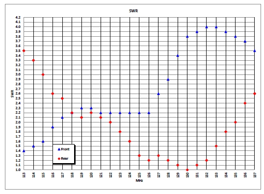
[img]cid:7.1.0.9.0.20191028104902.06ca0978(at)aeroelectric.com.0[/img]
| Quote: | | As you can see in the attached graphs, impedance is all over the map, and rarely near 50 ohms. The SWR seems to indicate that the front antenna is barely tolerable up to 127 MHz, above which it gets pretty bad. Conversely, the tail antenna is pretty crappy until 116 MHz, then tolerable right up to 135 MHz. |
The aft antenna (vertical fin?) does show a smooth
curve with pronounced dip at 130MHz. This suggest
the antenna is doing a reasonable job of accepting
energy from the feedline over the range of interest.
Further, it's under 3:1 SWR . . . I'd call it
good.
The front antenna plot suggests complete lack
of resonance at any point in the explored spectrum.
I'm assuming this antenna is wrapped around the
inside surface of the composite shell with a
predominantly vertical polarization.
If the SWR scan had been taken lower frequency,
I suspect that a pronounced dip in SWR would
be discovered . . . the trend of the plot as
it approaches 113Mhz suggests this.
It makes sense. Close proximity of either/both
CONDUCTIVE or DIELECTRIC features tend to
lower the resonant frequency of a radiator.
Pasting the antenna to the inside surface of
the fuselage will lower it's resonant frequency
measurably . . . proximity to steel structure
inside the fuselage will lower it more . . .
perhaps MUCH more.
Suggest the ends of the forward antenna be
shortened a bit and new scan taken . . . start
at some much lower frequency to see if there's
a real resonance artifact down there.I suspect that the interaction with conductive structure, such as the cage in front and the tail spar in the rear have more to do with the anomalies than the modest curvature. Not only that, the coax is connected to both antennas directly. Since the coax is an unbalanced conductor, and a dipole antenna is balanced, there is supposed to be something called a balun between them. I don't know if it was ignorance, cheapness, or weight-consciousness behind the absence of a balun, but no doubt thatâs also part of the problem.
A BALUN can improve on energy transfer between
feedline and antenna but the thing needs to be
RESONANT in the range of interest first.
I'm fiddling with an dual-band (121.5/406) ELT
antenna intended for installation on the inside
surface of an RF friendly composite fuselage. Looking
at the value of some BALUN options. Discoveries
would applied to the VHF comm antenna being
discussed here.
Get the SWR down and 'centered up' first.
Bob . . .
| | - The Matronics AeroElectric-List Email Forum - | | | Use the List Feature Navigator to browse the many List utilities available such as the Email Subscriptions page, Archive Search & Download, 7-Day Browse, Chat, FAQ, Photoshare, and much more:
http://www.matronics.com/Navigator?AeroElectric-List |
|
| Description: |
|
| Filesize: |
136.44 KB |
| Viewed: |
2074 Time(s) |
|
|
|
| Back to top |
|
 |
LouNathanson
Joined: 31 Oct 2019
Posts: 2
|
| Posted: Thu Oct 31, 2019 11:45 am Post subject: Re: Glastar Dipole comm antennae behind doors |
|
|
Thanks, Bob!  It had never occurred to me to step back and see the obvious:  that that front antenna was simply peaking well below the av band.  I will experiment with trimming it


I will also look forward to your balun.


Thanks,

-Lou
| | - The Matronics AeroElectric-List Email Forum - | | | Use the List Feature Navigator to browse the many List utilities available such as the Email Subscriptions page, Archive Search & Download, 7-Day Browse, Chat, FAQ, Photoshare, and much more:
http://www.matronics.com/Navigator?AeroElectric-List |
|
|
|
| Back to top |
|
|
|
|
You cannot post new topics in this forum
You cannot reply to topics in this forum
You cannot edit your posts in this forum
You cannot delete your posts in this forum
You cannot vote in polls in this forum
You cannot attach files in this forum
You can download files in this forum
|
Powered by phpBB © 2001, 2005 phpBB Group
|

