 |
Matronics Email Lists
Web Forum Interface to the Matronics Email Lists
|
| View previous topic :: View next topic |
| Author |
Message |
rj_todd(at)yahoo.co.uk
Guest
|
 Posted: Fri May 09, 2008 12:42 am Post subject: Rudder Trim - Spring Bias Posted: Fri May 09, 2008 12:42 am Post subject: Rudder Trim - Spring Bias |
 |
|
Hi Jason,
I was wondering how you are going with the development of the rudder trim?
Best wishes,
Rodger
--- On Fri, 22/2/08, jason.kreidler(at)regalbeloit.com <jason.kreidler(at)regalbeloit.com> wrote:
| Quote: | From: jason.kreidler(at)regalbeloit.com <jason.kreidler(at)regalbeloit.com>
Subject: Rudder Trim - Spring Bias
To: rv10-list(at)matronics.com
Date: Friday, 22 February, 2008, 6:55 PM
I have 'developed' a spring bias rudder trim system
for the RV-10. After
sharing this idea with Deems he encouraged me to do the
same with the rest
of the group. So here goes, but before I get into any
details let me
preface this whole conversation with a few thoughts. This
is all in
theory, I have absolutely no actual flight testing to back
up any of the
'claims', or assumptions. Just good old common
sense and a tiny bit of
engineering. Our airplane is not in the air yet, I had
hoped to get in
the air, prove out the system, then share with the world.
To prevent
anyone else for possibly needlessly cutting into their
rudder to add a
trim tab, I have decided to bear the scrutiny of an
unproven, theoretical
system. Please be gentle...
I will attempt to verbalize the system. I used two torsion
springs, one
mounted / wrapped around, each rudder bar (the bar that
connects the
rudder pedals). One of the springs is fixed on both ends
providing a
torsional force on the rudder bar. The other springs free
end is hooked
to a servo motor that allows approximately 30 degrees
deflection. The
theory is that the two springs will seek equilibrium (OK,
that's not much
theory, that's more fact), here is where the testing
needs to happen. If
I deflect the one springs free arm 30 degrees, will it
create enough force
to put the airplane in trim. The springs apply about an 8
pound force to
the rudder cables (pre-load if you will), assuming they
will want to
maintain in equilibrium a 30 degree deflection should be
more than enough
to trim the airplane. The servo will act as sort of a fine
tuning
mechanism, the course adjustment will be accomplished by
winding more or
less tension in one spring or the other during flight
testing.
I like a few things about this method.
1) It can be installed to any flying airplane with no
modifications
required other than wiring.
2) There is a chance that this system could be made manual
and eliminate
the RAC servo if desired.
3) This system provides tension to both rudder cables, no
more 'flopping
rudder'.
4) Keeps the rudder 'clean'.
5) Doesn't add much extra rudder input force.
I sent pictures of this system to Deems, I will
'attempt' to post some
pictures to this forum if there is interest. Comments
welcome, I
apologize for the extremely long post, but I have added
Deems questions
below, I figured if he asked, many more will have the same
questions....
1. How did you determine which spring type/size/strength to
use?
OK, you busted me!! I didn't do the math, I feel
extremely guilty about
this, as an engineer, I should probably go back and figure
the forces
here. Here is what I did; since I grew up in the business
of garage doors
(my Dad owned his own company doing this), I went to Fleet
Farm (one of
our local supply houses, similar to most lumbar yards) and
found a garage
door spring that had an ID that would slide over the rudder
bar with room
to spare, and would fit between the two rudder bars (I will
measure this
for you). I then cut lengths of the spring until I got
what I 'thought'
was a reasonable amount of force with two turns of
pre-load, and bent some
custom ends on them. With torsion springs you have two
options to
increase the reaction force. You can add turns of
pre-load, or you can
shorten the spring with the same number of turns. I just
went until I
reached what I 'felt' was a happy medium. Remember
that as you wind a
torsion spring more and more the inside diameter decreases,
until it
eventually binds on the shaft (rudder bar). What mostly
drove me not to
do the math, was I had absolutely no idea what sort of
corrective rudder
pressure was required to put the ball in the middle. My
plan all along
has been to get it in the air and do some experimenting, I
installed the
system so that modification of the spring force should be
simple. I just
need to start dating a contortionist 
2. I assume that you can 'adjust the torsional load
somewhat by moving
the collar/s, Is that true?
Correct, I started out with each spring wound an equal
amount. If I find
that I need additional trim to one side or the other I will
wind one of
the springs to compensate. The servo will just provide the
'fine tuning'.
3. One of the pictures shows the center support brace minus
the delrin
bushings, I'm assuming that leaving those out is not a
requirement of
your approach and was just the result of taking the picture
before they
were installed?
Correct, in fact there isn't a single modification to
the airframe, if I
remove the system no one could ever tell it was installed.
I built the
mount so that it could be used in either the forward or aft
rudder
mounting positions, my pedals are mounted in the aft
position. But I
drilled and prepped the airframe to mount the rudder pedals
in either
position.
4. What about the mount for the RAC servo, do you have a
picture of it
before the servo is mounted.
See attached.... The angle was determined by something, I
just don't
recall what anymore. I know it has to be at an angle to
work though. I
can measure if you decide to attempt this.
5. Also it' looks like you used a small section of SS
cable to connect
the servo arm to the spring coil, correct? Picture?
Correct, see attached. One end is run through the servo
arm, the other
gets hooked by the spring. The spring on the pilot side is
hooked over
the opposite rudder bar.
I gave some thought to your desire to have a manually
operated system, I
think this system could be done manually with very little
pain. You may
be able to add a knob that would come out of the sub panel,
really
anywhere along its length. What would have to happen is a
bracket would
need to be made that slid over the rudder bar with a nut in
it. Then a
threaded shaft running from the rudder bar to the sub panel
would be used
to adjust the free arm of the spring. It may be best if
the spring were
pushed by the shaft instead of pulled, as this would make
the mechanism a
bit simpler. I could do a drawing of what I am thinking if
you are not
following.
While it was not my intention to begin producing kits, if
there is enough
interest, I could be persuaded to fabricate a few.
Thanks, Jason
Jason Kreidler - 40617 Finishing
(4 Partner Build)
|
__________________________________________________________
Sent from Yahoo! Mail.
A Smarter Email http://uk.docs.yahoo.com/nowyoucan.html
| | - The Matronics RV10-List Email Forum - | | | Use the List Feature Navigator to browse the many List utilities available such as the Email Subscriptions page, Archive Search & Download, 7-Day Browse, Chat, FAQ, Photoshare, and much more:
http://www.matronics.com/Navigator?RV10-List |
|
|
|
| Back to top |
|
 |
jkreidler
Joined: 13 Feb 2008
Posts: 151
Location: Sheboygan Falls WI
|
| Posted: Mon May 12, 2008 4:09 am Post subject: Rudder Trim - Spring Bias |
|
|
All, I have received several off-line inquiries as to the status of the development of the spring bias rudder trim system.  The work continues however, it has gone down an unexpected path.  Since receiving so many requests for kits, I decided it would be best to put pencil to paper and actually calculate the trim forces we could expect to see.  Well, numbers don't lie (if you ask the right question), and the numbers didn't look good.  The maximum trim force I could accomplish given the limits of the servo motor both in stroke, and thrust, is 2lbs.


This is far below the value required to effectively trim the aircraft through a wide range of the flight envelope.  Van's estimated the required forces to be 5-10 lbs for 'standard' trim, and 25 lbs for takeoff measured at the bottom of the rudder pedal.  I had a conversation with Ken from Vans at Sun-N-Fun, I asked him "If you were going to design a rudder trim for the 10 what would it look like?".  Long answer short, he would design a spring bias system, he would not add a movable trim tab to the rudder due to the potential to put the rudder out of balance.  Please note, I am not trying to start a war here on the better way to add trim, just relaying what I was told.  He liked a spring system because it holds a bit of pressure on the rudder, which could eliminate some adverse yaw in turbulence.  I asked him why they haven't designed a system yet, and he first replied, we really don't think it is necessary, he then said that he has tried a few times and couldn't come up with a simple enough solution.


So, what does this all mean?  After seeing the post by Albert Gardner I started to rethink the concept.  I liked the idea of using extension springs, as they would allow the forces acting on the servo to stay within limits, while providing 10+ lbs of trim force.  I still like the idea of keeping the rudder cables under tension throughout the system, this means the springs still need to be connected up-front.  I have some ideas, but have not assemble the complete concept yet.  Unfortunately it will not be as simple, which is a big negative in my book, I really like simple!


All is not lost, if a person does not want rudder trim, but is tired of 'floppy rudder syndrome' the torsion springs provide enough force.  They can be wound during installation to accomplish a certain fixed trim force, eliminating the need to glue a trim block to the rudder.  I will let everyone know how this all turns out.  Sorry for not sending an update earlier, but I have been trying to get a complete answer before posting something again.


 Thanks, Jason Kreidler

N44YH - #40617 - Finishing

4 Partner Build

Jason Kreidler, Tony Kolar, Kyle Hokel, and Wayne Elsner

Sheboygan Falls, WI [quote][b]
| | - The Matronics RV10-List Email Forum - | | | Use the List Feature Navigator to browse the many List utilities available such as the Email Subscriptions page, Archive Search & Download, 7-Day Browse, Chat, FAQ, Photoshare, and much more:
http://www.matronics.com/Navigator?RV10-List |
|
_________________
Jason Kreidler
4 Partner Build - Sheboygan Falls, WI
Tony Kolar, Kyle Hokel, Wayne Elser, Jason Kreidler
N44YH - Flying - #40617 |
|
| Back to top |
|
|
pitts_pilot(at)bellsouth.
Guest
|
| Posted: Mon May 12, 2008 5:14 am Post subject: Rudder Trim - Spring Bias |
|
|
I was going to reply off-line but decided that maybe more ideas can be generated as a group:
jason.kreidler(at)regalbeloit.com (jason.kreidler(at)regalbeloit.com) wrote: | Quote: |
All, I have received several off-line inquiries as to the status of the development of the spring bias rudder trim system. The work continues however, it has gone down an unexpected path. Since receiving so many requests for kits, I decided it would be best to put pencil to paper and actually calculate the trim forces we could expect to see. Well, numbers don't lie (if you ask the right question), and the numbers didn't look good. The maximum trim force I could accomplish given the limits of the servo motor both in stroke, and thrust, is 2lbs.
|
I assume, from the statement below that this only applies to the torsion spring design ..... so why not a small jackscrew instead of a trim servo?
SNIP
| Quote: | So, what does this all mean? After seeing the post by Albert Gardner I started to rethink the concept. I liked the idea of using extension springs, as they would allow the forces acting on the servo to stay within limits, while providing 10+ lbs of trim force. I still like the idea of keeping the rudder cables under tension throughout the system, this means the springs still need to be connected up-front. I have some ideas, but have not assemble the complete concept yet. Unfortunately it will not be as simple, which is a big negative in my book, I really like simple!
|
Simple is always good! I think if there was a simple solution, it would have shown up already. There are a lot of great minds out there so there should have been something pop up .... even if it wasn't a really great solution, it would be a start.
| Quote: | | All is not lost, if a person does not want rudder trim, but is tired of 'floppy rudder syndrome' the torsion springs provide enough force. |
I've never had an airplane with the 'floppy rudder syndrome' ..... and really don't want to start now. I own a Grumman AA-1B with rudder springs ...... the only problem with them is that they're really strong springs and they break ...... but folks smarter than me have devised a 'washer' tool to aid in changing them out. The springs really cure the 'floppy rudder syndrome' which means we have to incorporate a good rudder gust lock to tame the beast. I've modified my rudder pedal attach point to be inside the tunnel, (don't like sand and dirt on my cables) and have thought of a pulley attached to the firewall to make a closed loop system .... or extension springs to the firewall ...... after I find a good spot and beef it up a little. Alas, I just don't have a good answer.
| Quote: | | They can be wound during installation to accomplish a certain fixed trim force, eliminating the need to glue a trim block to the rudder. I will let everyone know how this all turns out. |
Thanks for your time/effort. Other than the jackscrew solution, I'm not much help.
| Quote: | Sorry for not sending an update earlier, but I have been trying to get a complete answer before posting something again.
|
Rome wasn't built in a day (although I wasn't there to figure out why  ) and the solutions to difficult problems take time ..... and I'll really be thinking of a solution before I get too far down the assembly path where it's nigh on impossible to install a mod. ) and the solutions to difficult problems take time ..... and I'll really be thinking of a solution before I get too far down the assembly path where it's nigh on impossible to install a mod.
Linn
do not archive
[quote]
Thanks, Jason Kreidler
N44YH - #40617 - Finishing
4 Partner Build
Jason Kreidler, Tony Kolar, Kyle Hokel, and Wayne Elsner
Sheboygan Falls, WI | Quote: |
href="http://www.matronics.com/Navigator?RV10-List">http://www.matronics.com/Navigator?RV10-List
href="http://forums.matronics.com">http://forums.matronics.com
href="http://www.matronics.com/contribution">http://www.matronics.com/contribution
|
[b]
| | - The Matronics RV10-List Email Forum - | | | Use the List Feature Navigator to browse the many List utilities available such as the Email Subscriptions page, Archive Search & Download, 7-Day Browse, Chat, FAQ, Photoshare, and much more:
http://www.matronics.com/Navigator?RV10-List |
|
|
|
| Back to top |
|
|
dlm46007(at)cox.net
Guest
|
| Posted: Mon May 12, 2008 5:38 am Post subject: Rudder Trim - Spring Bias |
|
|
What kinds of problems have been seen with the glued tab or the riveted tab other than it has only a cruise airspeed setting?
From: owner-rv10-list-server(at)matronics.com [mailto:owner-rv10-list-server(at)matronics.com] On Behalf Of linn Walters
Sent: Monday, May 12, 2008 5:51 AM
To: rv10-list(at)matronics.com
Subject: Re: Rudder Trim - Spring Bias
I was going to reply off-line but decided that maybe more ideas can be generated as a group:
jason.kreidler(at)regalbeloit.com (jason.kreidler(at)regalbeloit.com) wrote: | Quote: |
All, I have received several off-line inquiries as to the status of the development of the spring bias rudder trim system. The work continues however, it has gone down an unexpected path. Since receiving so many requests for kits, I decided it would be best to put pencil to paper and actually calculate the trim forces we could expect to see. Well, numbers don't lie (if you ask the right question), and the numbers didn't look good. The maximum trim force I could accomplish given the limits of the servo motor both in stroke, and thrust, is 2lbs.
|
I assume, from the statement below that this only applies to the torsion spring design ..... so why not a small jackscrew instead of a trim servo?
SNIP
| Quote: | So, what does this all mean? After seeing the post by Albert Gardner I started to rethink the concept. I liked the idea of using extension springs, as they would allow the forces acting on the servo to stay within limits, while providing 10+ lbs of trim force. I still like the idea of keeping the rudder cables under tension throughout the system, this means the springs still need to be connected up-front. I have some ideas, but have not assemble the complete concept yet. Unfortunately it will not be as simple, which is a big negative in my book, I really like simple!
|
Simple is always good! I think if there was a simple solution, it would have shown up already. There are a lot of great minds out there so there should have been something pop up .... even if it wasn't a really great solution, it would be a start.
| Quote: | | All is not lost, if a person does not want rudder trim, but is tired of 'floppy rudder syndrome' the torsion springs provide enough force. |
I've never had an airplane with the 'floppy rudder syndrome' ..... and really don't want to start now. I own a Grumman AA-1B with rudder springs ..... the only problem with them is that they're really strong springs and they break ..... but folks smarter than me have devised a 'washer' tool to aid in changing them out. The springs really cure the 'floppy rudder syndrome' which means we have to incorporate a good rudder gust lock to tame the beast. I've modified my rudder pedal attach point to be inside the tunnel, (don't like sand and dirt on my cables) and have thought of a pulley attached to the firewall to make a closed loop system .... or extension springs to the firewall ..... after I find a good spot and beef it up a little. Alas, I just don't have a good answer.
| Quote: | | They can be wound during installation to accomplish a certain fixed trim force, eliminating the need to glue a trim block to the rudder. I will let everyone know how this all turns out. |
Thanks for your time/effort. Other than the jackscrew solution, I'm not much help.
| Quote: | Sorry for not sending an update earlier, but I have been trying to get a complete answer before posting something again.
|
Rome wasn't built in a day (although I wasn't there to figure out why ) and the solutions to difficult problems take time ..... and I'll really be thinking of a solution before I get too far down the assembly path where it's nigh on impossible to install a mod.
Linn
do not archive
[quote]
Thanks, Jason Kreidler
N44YH - #40617 - Finishing
4 Partner Build
Jason Kreidler, Tony Kolar, Kyle Hokel, and Wayne Elsner
Sheboygan Falls, WI | Quote: |
href="http://www.matronics.com/Navigator?RV10-List">http://www.matronics.com/Navigator?RV10-List
href="http://forums.matronics.com">http://forums.matronics.com
href="http://www.matronics.com/contribution">http://www.matronics.com/contribution
|
href="http://www.matronics.com/Navigator?RV10-List">http://www.matronics.com/Navigator?RV10-List
href="http://forums.matronics.com">http://forums.matronics.com
href="http://www.matronics.com/contribution">http://www.matronics.com/c
[b]
| | - The Matronics RV10-List Email Forum - | | | Use the List Feature Navigator to browse the many List utilities available such as the Email Subscriptions page, Archive Search & Download, 7-Day Browse, Chat, FAQ, Photoshare, and much more:
http://www.matronics.com/Navigator?RV10-List |
|
|
|
| Back to top |
|
|
MauleDriver(at)nc.rr.com
Guest
|
| Posted: Mon May 12, 2008 6:12 am Post subject: Rudder Trim - Spring Bias |
|
|
I haven't been following this real closely but am very interested in

working solution ... excuse me if this has been covered.


Since servo force required is an issue, have you considered a totally

manual/mechanical system?   For example, actuation via a pull on

T-handle with a  twist to lock mechanism.  This is what my Maule uses

though I am only familiar with the operation of it, not the design.


Bill "bonding doors" Watson

Durham

do not archive
| | - The Matronics RV10-List Email Forum - | | | Use the List Feature Navigator to browse the many List utilities available such as the Email Subscriptions page, Archive Search & Download, 7-Day Browse, Chat, FAQ, Photoshare, and much more:
http://www.matronics.com/Navigator?RV10-List |
|
|
|
| Back to top |
|
|
ogdenk
Joined: 05 Feb 2007
Posts: 41
Location: Syracuse, NY
|
| Posted: Mon May 12, 2008 6:22 am Post subject: Rudder Trim - Spring Bias |
|
|
Jason,
Although I am quite early in the build, I have followed the rudder trim threads with interest and I thought that the torsion spring was a great idea. I was afraid that the linear servo approach might not work though, and am sorry to hear your results. The reason it doesn't work, as you found, is that the torque gradient (amount of torque per unit angular displacement) of the torsion spring is too low, so the linear servo can't produce enough displacement to generate the required force. The thing is, the low torque gradient is necessary or a large force from the pilots leg will be required to fully displace the rudder pedal.
I think this could be made to work in the same way that my garage door tensioner works. It uses a worm gear to drive another gear that is fixed to the end of the spring. You stick a hex driver in the end of the worm gear and turn it with an electric drill to tension the torsion spring. The amount of rotation of the spring is essentially unlimited using this method. The ratio of the worm gear rotations to torsion spring rotations is high, so any typical electric drill can provide enough torque to tension the spring.
The analog for the rudder trim would be a 'rotary' servo (not sure if this is correct terminology, I don't see this kind of thing on the Ray Allen web site) that could spin a worm gear in either direction, driving a second gear that is coaxial to and attached to the torsion spring, to tension the spring. Much more complicated than what you tried, but I still like it better (at this point at least) than chopping up my rudder to add a trim system. Nothing beats the simplicity of a trim tab though!
Kent Ogden
#40710 Tailcone
| Quote: | >> <jason.kreidler(at)regalbeloit.com> 5/12/2008 8:03 AM >>>
|
All, I have received several off-line inquiries as to the status of the development of the spring bias rudder trim system.
<<SNIPPED>>
Thanks, Jason Kreidler
N44YH - #40617 - Finishing
4 Partner Build
Jason Kreidler, Tony Kolar, Kyle Hokel, and Wayne Elsner
Sheboygan Falls, WI
| | - The Matronics RV10-List Email Forum - | | | Use the List Feature Navigator to browse the many List utilities available such as the Email Subscriptions page, Archive Search & Download, 7-Day Browse, Chat, FAQ, Photoshare, and much more:
http://www.matronics.com/Navigator?RV10-List |
|
|
|
| Back to top |
|
|
Deems Davis
Joined: 09 Jan 2006
Posts: 925
|
| Posted: Mon May 12, 2008 6:47 am Post subject: Rudder Trim - Spring Bias |
|
|
I just returned from The NW RV-10 builders semi annual dinner/get
together. There were 6-7 RV-10's that flew in for it. Among them was
Bill & Susie DeRouchey's plane from So Calif. Bill showed us his
solution for rudder trim. I was blown away !!!!! It is similar in
concept to what Bill Watson is suggesting, it is _elegantly simple_,
easy to implement and very effective. and has some benefits beyond trim.
I don't want to steal Bill's thunder so I'll wait for him to respond
directly. Bill and Susie are probably flying back home and it may be a
day or two before he's back on the list. When he reads this I'm hoping
he'll post some pictures and additional information. (I left my camera
in the bag in my room and couldn't take any pics).
MauleDriver wrote:
| Quote: |
considered a totally manual/mechanical system? For example,
actuation via a pull on T-handle with a twist to lock mechanism.
|
PS. You should also see what the artistry and engineering of Paul
Grimstad has developed? (I'm salivating over it!!!!!!!!!)
Deems Davis # 406
'Its all done....Its just not put together'
http://deemsrv10.com/
| | - The Matronics RV10-List Email Forum - | | | Use the List Feature Navigator to browse the many List utilities available such as the Email Subscriptions page, Archive Search & Download, 7-Day Browse, Chat, FAQ, Photoshare, and much more:
http://www.matronics.com/Navigator?RV10-List |
|
|
|
| Back to top |
|
|
jkreidler
Joined: 13 Feb 2008
Posts: 151
Location: Sheboygan Falls WI
|
| Posted: Tue May 13, 2008 5:36 am Post subject: Rudder Trim - Spring Bias |
|
|
A few response rolled into one.


"so why not a small jackscrew instead of a trim servo?"

If I could find something light, inexpensive, and simple, it would certainly be an option.  Anyone have a source?


"What kinds of problems have been seen with the glued tab or the riveted tab other than it has only a cruise airspeed setting?"

Absolutely no problems at all, rudder trim may not be high on some lists, but it is on mine.  The fixed trim offers great benefit (extremely simple), at of course a price (fixed trim).  I know others have decided not to install trim, still others have cut into a perfectly good painted rudder to add trim.  Like any option it is a personal choice.


"Since servo force required is an issue, have you considered a totally manual/mechanical system?"

Yes, just haven't found a cute, light way of doing it.  However, electric means it can be buried in any orientation at any location, opening up more mounting options.  A manual system would be a real benefit, as I know a few are looking for a manual system.


"I think this could be made to work in the same way that my garage door tensioner works."

This would be an great approach, the question is where to get something like this?


The great thing about sharing ideas is the collaboration.  Many of us have obviously been thinking of different approaches to this 'problem'.  In looking over Bill DeRouchey's approach I got to thinking...


I think the secret to making this really simple is to start with a completely closed loop system.  So what would happen if we mounted a pulley to the firewall centered between the left and right rudder pedals on either the pilot or copilot side of the aircraft.  Then connect a cable to the two pedals routed through the pulley.  This gets us a closed loop system.


Next we use Bill's concept, with a few changes.  Since we now have a closed loop, we only need to act on one of the rudder cables.  So instead of clamping the cable, we clamp two springs to the cable (about 12 inches apart), these two springs are then hooked in the middle to the knob that passes through the tunnel wall.  The tunnel wall is slotted, allowing the knob to move fore and aft.  So to adjust the trim you would loosen the knob slide it back until you center the ball, then re-tighten the knob.  The springs would still allow full use of the rudder, and the world is in perfect harmony.  Well, at least the ball is in the center.


I wonder if the cable needs to be supported between the springs, I keep thinking that the springs would just want to pull together leaving the cable slack between the springs.  Maybe since the system is now closed, the two trim springs would act as a 'slack take-up'.  Also, not sure if there is enough room to fit the forward spring, and still keep the knob where it can be reached.


What I like is the fact that we can now have either manual or electric trim.  In addition this certainly meets the simple, and relatively easy to install criteria.  Any thoughts?


Thanks, Jason Kreidler

 N44YH - #40617 - Finishing

 4 Partner Build

 Jason Kreidler, Tony Kolar, Kyle Hokel, and Wayne Elsner

 Sheboygan Falls, WI [quote][b]
| | - The Matronics RV10-List Email Forum - | | | Use the List Feature Navigator to browse the many List utilities available such as the Email Subscriptions page, Archive Search & Download, 7-Day Browse, Chat, FAQ, Photoshare, and much more:
http://www.matronics.com/Navigator?RV10-List |
|
_________________
Jason Kreidler
4 Partner Build - Sheboygan Falls, WI
Tony Kolar, Kyle Hokel, Wayne Elser, Jason Kreidler
N44YH - Flying - #40617 |
|
| Back to top |
|
|
pitts_pilot(at)bellsouth.
Guest
|
| Posted: Tue May 13, 2008 9:35 am Post subject: Rudder Trim - Spring Bias |
|
|
jason.kreidler(at)regalbeloit.com (jason.kreidler(at)regalbeloit.com) wrote: | Quote: |
A few response rolled into one.
"so why not a small jackscrew instead of a trim servo?"
If I could find something light, inexpensive, and simple, it would certainly be an option. Anyone have a source?
|
I'll google and see what I can find ..... after all, it was my suggestion.
| Quote: |
"What kinds of problems have been seen with the glued tab or the riveted tab other than it has only a cruise airspeed setting?"
|
None that I know of. I'm operating in the dark here so just giving it some thought ..... the fixed trim works best at one cruise speed .... and at one density altitude .....
| Quote: | Absolutely no problems at all, rudder trim may not be high on some lists, but it is on mine. The fixed trim offers great benefit (extremely simple), at of course a price (fixed trim). I know others have decided not to install trim, still others have cut into a perfectly good painted rudder to add trim. Like any option it is a personal choice.
|
Absolutely. That is, I guess, the crux of my problem ..... the decision on what path to go is purely subjective on the part of the builder taking that path. I felt that any good autopilot should be able to handle the trim problem, but others tell me the autopilot will either disconnect or the servo's will, at swome point, lock up or slip.
| Quote: | "Since servo force required is an issue, have you considered a totally manual/mechanical system?"
Yes, just haven't found a cute, light way of doing it. However, electric means it can be buried in any orientation at any location, opening up more mounting options. A manual system would be a real benefit, as I know a few are looking for a manual system. |
A simple solution is hampered by the fact the pedals flop. the closed loop solution (below) really makes the difficult part go away.
| Quote: | "I think this could be made to work in the same way that my garage door tensioner works."
This would be an great approach, the question is where to get something like this?
The great thing about sharing ideas is the collaboration. Many of us have obviously been thinking of different approaches to this 'problem'. In looking over Bill DeRouchey's approach I got to thinking...
I think the secret to making this really simple is to start with a completely closed loop system. So what would happen if we mounted a pulley to the firewall centered between the left and right rudder pedals on either the pilot or copilot side of the aircraft. Then connect a cable to the two pedals routed through the pulley. This gets us a closed loop system.
Next we use Bill's concept, with a few changes. Since we now have a closed loop, we only need to act on one of the rudder cables. So instead of clamping the cable, we clamp two springs to the cable (about 12 inches apart), these two springs are then hooked in the middle to the knob that passes through the tunnel wall. The tunnel wall is slotted, allowing the knob to move fore and aft. So to adjust the trim you would loosen the knob slide it back until you center the ball, then re-tighten the knob. The springs would still allow full use of the rudder, and the world is in perfect harmony. Well, at least the ball is in the center.
I wonder if the cable needs to be supported between the springs, I keep thinking that the springs would just want to pull together leaving the cable slack between the springs. Maybe since the system is now closed, the two trim springs would act as a 'slack take-up'. Also, not sure if there is enough room to fit the forward spring, and still keep the knob where it can be reached.
What I like is the fact that we can now have either manual or electric trim. In addition this certainly meets the simple, and relatively easy to install criteria. Any thoughts?
|
A simple (in my mind, anyway) would be to make the rudder system closed loop. This will allow the two-springs on one cable possible. Next we put the end of a vernier control cable on the center of the two springs .... and we can adjust the tension on the springs to bias the rudder. How well it works is dependent on the tension and length of the springs. I have to admit I'm not a fan of the 'gripped cable' mod but I do admire it's simplicity.
Linn
do not archive
[quote]
Thanks, Jason Kreidler
N44YH - #40617 - Finishing
4 Partner Build
Jason Kreidler, Tony Kolar, Kyle Hokel, and Wayne Elsner
Sheboygan Falls, WI | Quote: |
href="http://www.matronics.com/Navigator?RV10-List">http://www.matronics.com/Navigator?RV10-List
href="http://forums.matronics.com">http://forums.matronics.com
href="http://www.matronics.com/contribution">http://www.matronics.com/contribution
|
[b]
| | - The Matronics RV10-List Email Forum - | | | Use the List Feature Navigator to browse the many List utilities available such as the Email Subscriptions page, Archive Search & Download, 7-Day Browse, Chat, FAQ, Photoshare, and much more:
http://www.matronics.com/Navigator?RV10-List |
|
|
|
| Back to top |
|
|
Albert Gardner

Joined: 10 Jan 2006
Posts: 455
Location: Yuma, AZ
|
| Posted: Wed May 14, 2008 9:13 pm Post subject: Rudder Trim - Spring Bias |
|
|
I have been doing a little testing of my spring bias trim system. I did not

measure rudder pedal forces required but the spring bias system has almost

enough force on take off so that only a little right rudder pressure is

required and the same for slow flight. Otherwise for normal climb, cruise

and descents the trim system will center the ball. It was easy to install as

Vans aileron trim servo is used as is and 4 holes drilled in the bottom of

the tail cone to install it. The turn around pulley bracket is simple to

fabricate and bolts to the elevator bell crank housing assy. The hardest

part was pulling additional rudder cables from the trim servo arm back to

the rudder horn. Also, having 2 rudder cables attached to the rudder horn is

the one thing I don't like about the system. I already had a 5 wire cable

installed in the tail come anticipating rudder trim at some later point when

I built the plane and a Ray Allen LED trim indicator and switch on the panel

with wiring completed. The trim forces are fairly easy to overcome so run

away trim doesn't seem to be a big worry. All in all I'm very happy with the

system. Frankly, the idea of clamping the rudder cables to effect trim seems

difficult for me to accept.

Albert Gardner

N991RV

Yuma, AZ
| | - The Matronics RV10-List Email Forum - | | | Use the List Feature Navigator to browse the many List utilities available such as the Email Subscriptions page, Archive Search & Download, 7-Day Browse, Chat, FAQ, Photoshare, and much more:
http://www.matronics.com/Navigator?RV10-List |
|
_________________
RV-9A N872RV
RV-10 N991RV |
|
| Back to top |
|
|
pitts_pilot(at)bellsouth.
Guest
|
| Posted: Thu May 15, 2008 4:56 am Post subject: Rudder Trim - Spring Bias |
|
|
I'm sure there are more than a few that would like to see some pictures!!!
Linn
do not archive
Albert Gardner wrote:
| Quote: |
I have been doing a little testing of my spring bias trim system. I did not
measure rudder pedal forces required but the spring bias system has almost
enough force on take off so that only a little right rudder pressure is
required and the same for slow flight. Otherwise for normal climb, cruise
and descents the trim system will center the ball. It was easy to install as
Vans aileron trim servo is used as is and 4 holes drilled in the bottom of
the tail cone to install it. The turn around pulley bracket is simple to
fabricate and bolts to the elevator bell crank housing assy. The hardest
part was pulling additional rudder cables from the trim servo arm back to
the rudder horn. Also, having 2 rudder cables attached to the rudder horn is
the one thing I don't like about the system. I already had a 5 wire cable
installed in the tail come anticipating rudder trim at some later point when
I built the plane and a Ray Allen LED trim indicator and switch on the panel
with wiring completed. The trim forces are fairly easy to overcome so run
away trim doesn't seem to be a big worry. All in all I'm very happy with the
system. Frankly, the idea of clamping the rudder cables to effect trim seems
difficult for me to accept.
Albert Gardner
N991RV
Yuma, AZ
|
| | - The Matronics RV10-List Email Forum - | | | Use the List Feature Navigator to browse the many List utilities available such as the Email Subscriptions page, Archive Search & Download, 7-Day Browse, Chat, FAQ, Photoshare, and much more:
http://www.matronics.com/Navigator?RV10-List |
|
|
|
| Back to top |
|
|
Tim Olson
Joined: 25 Jan 2007
Posts: 2882
|
| Posted: Thu May 15, 2008 12:18 pm Post subject: Rudder Trim - Spring Bias |
|
|
Don Orrick sent me some photos and info on a rudder trim setup
that he's using in his RV-10. It's got a vernier control and
doesn't lock any cables anytime. He admits it to be slightly
crude as it's a proof-of-concept that he actually has flying,
but it could be cleaned up to be pretty nice if someone wanted
it different. I'm just passing on the info to you all in case
you like the idea.
It's in my Tips area at: (with photos)
http://www.myrv10.com/tips/mods/RudderTrim/DonOrrick.html
I'm surprised at how long the rudder trim thread lasts. It
seems to me that there are just so many ideas to ponder.
Personally, the electric servo trim tab seems pretty
simple and straightforward and actually took very little
effort and time to install...and I left the rudder on
the plane to do it, so I'm not sure why people spend tons
of time and effort on other ideas, but it's showing to be
a good thinking exercise at least. And between Albert
and Don, these systems are pretty true to the simple
rudder trim concept, without affecting rudder pedal function.
For me, a static wedge was pretty good for a long time.
The adjustable trim is very nice to have...and I personally
feel it's hard to beat a quick tap of a button to center
it...with no cable involvement at all.
Tim Olson - RV-10 N104CD - Flying
Albert Gardner wrote:
| Quote: |
I have been doing a little testing of my spring bias trim system. I did not
measure rudder pedal forces required but the spring bias system has almost
enough force on take off so that only a little right rudder pressure is
required and the same for slow flight. Otherwise for normal climb, cruise
and descents the trim system will center the ball. It was easy to install as
Vans aileron trim servo is used as is and 4 holes drilled in the bottom of
the tail cone to install it. The turn around pulley bracket is simple to
fabricate and bolts to the elevator bell crank housing assy. The hardest
part was pulling additional rudder cables from the trim servo arm back to
the rudder horn. Also, having 2 rudder cables attached to the rudder horn is
the one thing I don't like about the system. I already had a 5 wire cable
installed in the tail come anticipating rudder trim at some later point when
I built the plane and a Ray Allen LED trim indicator and switch on the panel
with wiring completed. The trim forces are fairly easy to overcome so run
away trim doesn't seem to be a big worry. All in all I'm very happy with the
system. Frankly, the idea of clamping the rudder cables to effect trim seems
difficult for me to accept.
Albert Gardner
N991RV
Yuma, AZ
|
| | - The Matronics RV10-List Email Forum - | | | Use the List Feature Navigator to browse the many List utilities available such as the Email Subscriptions page, Archive Search & Download, 7-Day Browse, Chat, FAQ, Photoshare, and much more:
http://www.matronics.com/Navigator?RV10-List |
|
|
|
| Back to top |
|
|
Albert Gardner
Joined: 10 Jan 2006
Posts: 455
Location: Yuma, AZ
|
| Posted: Thu May 15, 2008 2:42 pm Post subject: Rudder Trim - Spring Bias |
|
|
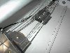
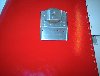
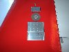
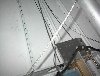
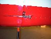
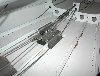
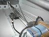
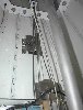
OK, here they are. Installation in the tail cone is straight forward. Bolt

the pulley bracket behind the elevator bellcrank using the aft 3 screws.

Build Vans aileron trim unit and locate the servo unit about half way

between the aft baggage bulkhead and the next one aft straddling the floor

stiffener. Fabricate 2 3/32" cables, one long enough to wrap around the

pulley. I left a 12" gap that the springs would bridge and provide bias

tension. Attach the cables to the rudder horn. Hook up the servo to the

switch and indicator. Fly. I added a keeper to the pulley bracket to insure

the cable could not  come off the pulley. It adds some small security for

gust protection on the ground but not enough to replace a gust lock.

Albert Gardner

N991RV

Yuma, AZ


--
| | - The Matronics RV10-List Email Forum - | | | Use the List Feature Navigator to browse the many List utilities available such as the Email Subscriptions page, Archive Search & Download, 7-Day Browse, Chat, FAQ, Photoshare, and much more:
http://www.matronics.com/Navigator?RV10-List |
|
| Description: |
|
| Filesize: |
38.14 KB |
| Viewed: |
282 Time(s) |
|
| Description: |
|
| Filesize: |
24.96 KB |
| Viewed: |
272 Time(s) |
|
| Description: |
|
| Filesize: |
25.48 KB |
| Viewed: |
288 Time(s) |
|
| Description: |
|
| Filesize: |
35.91 KB |
| Viewed: |
310 Time(s) |
|
| Description: |
|
| Filesize: |
24.78 KB |
| Viewed: |
315 Time(s) |
|
| Description: |
|
| Filesize: |
39.03 KB |
| Viewed: |
288 Time(s) |
|
| Description: |
|
| Filesize: |
38.19 KB |
| Viewed: |
300 Time(s) |

|
| Description: |
|
| Filesize: |
38.96 KB |
| Viewed: |
288 Time(s) |
|
| Description: |
|
| Filesize: |
25.59 KB |
| Viewed: |
285 Time(s) |
|
_________________
RV-9A N872RV
RV-10 N991RV |
|
| Back to top |
|
|
billderou(at)yahoo.com
Guest
|
| Posted: Thu May 15, 2008 5:02 pm Post subject: Rudder Trim - Spring Bias |
|
|
Albert-

  That is a very clean and foolproof installation.


  Bill DeRouchey

  N939SB, flying


Albert Gardner <ibspud(at)roadrunner.com> wrote:

  [quote]OK, here they are. Installation in the tail cone is straight forward. Bolt

the pulley bracket behind the elevator bellcrank using the aft 3 screws.

Build Vans aileron trim unit and locate the servo unit about half way

between the aft baggage bulkhead and the next one aft straddling the floor

stiffener. Fabricate 2 3/32" cables, one long enough to wrap around the

pulley. I left a 12" gap that the springs would bridge and provide bias

tension. Attach the cables to the rudder horn. Hook up the servo to the

switch and indicator. Fly. I added a keeper to the pulley bracket to insure

the cable could not come off the pulley. It adds  some small security for

gust protection on the ground but not enough to replace a gust lock.

Albert Gardner

N991RV

Yuma, AZ


--
| | - The Matronics RV10-List Email Forum - | | | Use the List Feature Navigator to browse the many List utilities available such as the Email Subscriptions page, Archive Search & Download, 7-Day Browse, Chat, FAQ, Photoshare, and much more:
http://www.matronics.com/Navigator?RV10-List |
|
|
|
| Back to top |
|
|
sam(at)fr8dog.net
Guest
|
| Posted: Fri May 16, 2008 5:09 am Post subject: Rudder Trim - Spring Bias |
|
|
Let's see the pic!


 Bill DeRouchey wrote: [quote]   Albert-

   That is a very clean and foolproof installation.


   Bill DeRouchey

   N939SB, flying


   Albert Gardner <ibspud(at)roadrunner.com> (ibspud(at)roadrunner.com) wrote:

   [quote]OK, here they are. Installation in the tail cone is straight forward. Bolt

 the pulley bracket behind the elevator bellcrank using the aft 3 screws.

 Build Vans aileron trim unit and locate the servo unit about half way

 between the aft baggage bulkhead and the next one aft straddling the floor

 stiffener. Fabricate 2 3/32" cables, one long enough to wrap around the

 pulley. I left a 12" gap that the springs would bridge and provide bias

 tension. Attach the cables to the rudder horn. Hook up the servo to the

 switch and indicator. Fly. I added a keeper to the pulley bracket to insure

 the cable could not come off the pulley. It adds some small security for

 gust protection on the ground but not enough to replace a gust lock.

 Albert Gardner

 N991RV

 Yuma, AZ


 --
| | - The Matronics RV10-List Email Forum - | | | Use the List Feature Navigator to browse the many List utilities available such as the Email Subscriptions page, Archive Search & Download, 7-Day Browse, Chat, FAQ, Photoshare, and much more:
http://www.matronics.com/Navigator?RV10-List |
|
|
|
| Back to top |
|
|
|
|
You cannot post new topics in this forum
You cannot reply to topics in this forum
You cannot edit your posts in this forum
You cannot delete your posts in this forum
You cannot vote in polls in this forum
You cannot attach files in this forum
You can download files in this forum
|
Powered by phpBB © 2001, 2005 phpBB Group
|

