 |
Matronics Email Lists
Web Forum Interface to the Matronics Email Lists
|
| View previous topic :: View next topic |
| Author |
Message |
RVPilot(at)mchsi.com
Guest
|
 Posted: Thu May 06, 2010 6:54 pm Post subject: Gear Leg Fairing Tip Posted: Thu May 06, 2010 6:54 pm Post subject: Gear Leg Fairing Tip |
 |
|
To my RV-Ten’r Colleagues –
I tend to stress about things that are not as complicated as they seem. In this case, how to simplify the alignment of the gear leg fairings?
Per Van’s plans, you need to create center lines, artificial center lines, Points, A, B, and X. Huh? What? This looks tough. Well it’s not if you are willing to spend $30 on something you can leave in your shop and use another day. Here is what I did.
- Drop a plumb bob from the front and rear of the plane, per plans, and snap a center line.
- From that center line, use a tape measure to measure out 27” from that center line on both sides at the front and at the rear of the plane. (Note: 27” was a perfect measurement for me!)
- Snap a chalk line, per plans on both sides.
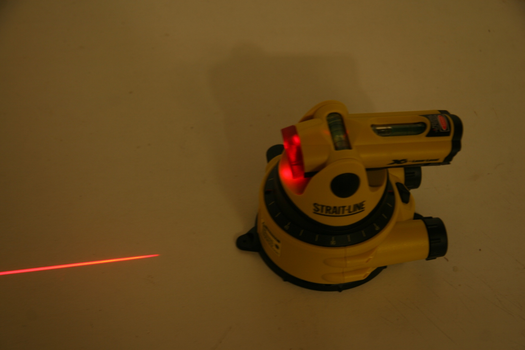
- Here’s the expensive part – Buy a laser like the one pictured for less than $30 – mine came from Home Depot.
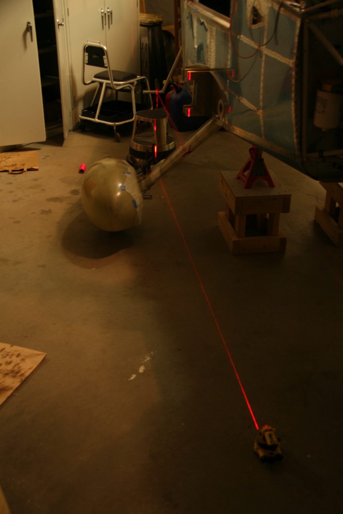
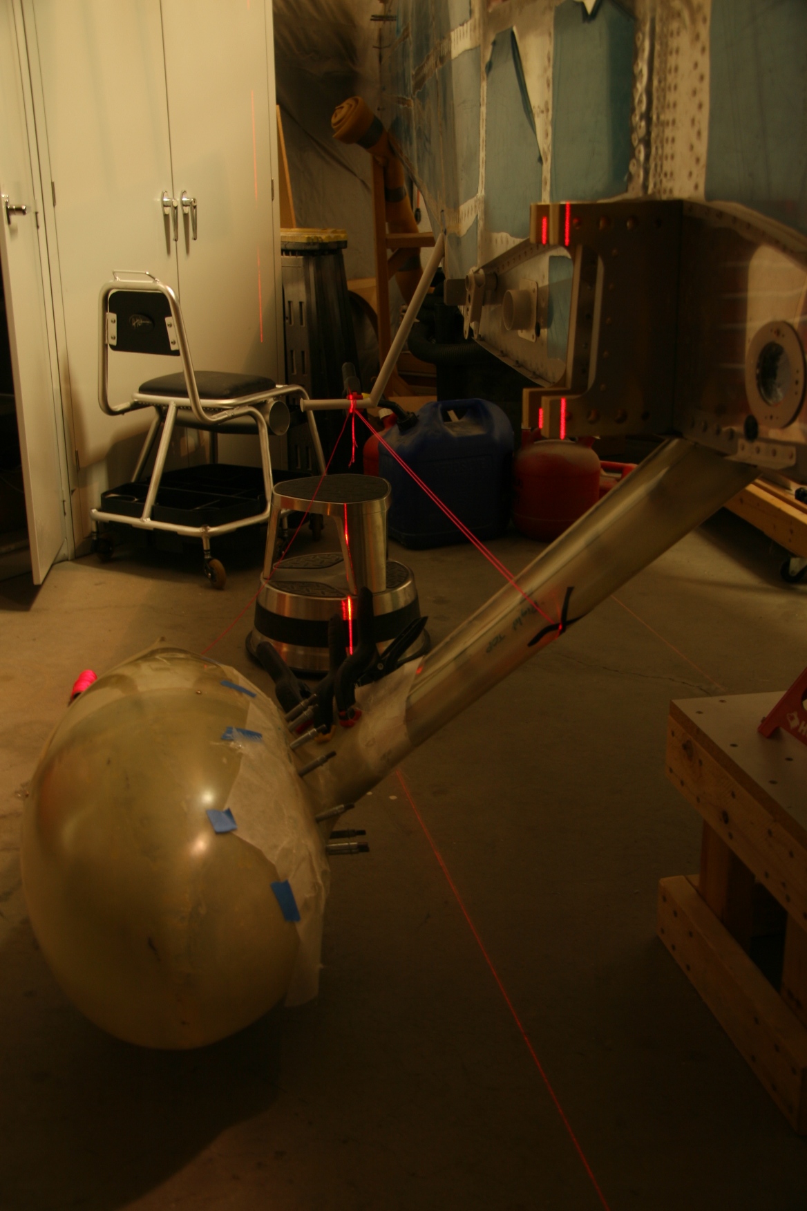
- Place the Laser at the front of the chalk line. Turn it on- Level the laser per the bubble guides on the laser itself.– and voila!!! A laser mark on the step, and the gear leg fairing IN THE RIGHT PLANE, PERFECTLY VERTICAL, and PERFECTLY PARALLEL to the center line. No plumb-bobbing from the step or fairing required!
- Stretch the strings - per plans off the bottom of the step where the laser light hits, around the gear leg fairing, where the laser light hits. Hold the string in place with small strips of electrical tape in a cross fashion per pictures attached.
- Measure up from the floor to both points of light. If the height does not match, adjust the laser left and right of the displaced center line of the chalk line. Keep in mind the step itself is level to the floor, so moving left and right of the chalk line moves the distance to the floor up and down as you move across the leg fairing. It’s easy to see if you are parallel to the line, as you can measure to and from the chalk line to the laser line. If none of this makes sense, it will be readily apparent once you set it all up.
- I got a fabulous/near perfect result, with very little effort in just a couple of minutes. 27” off centerline was exactly what I needed.
- The attached pictures have a stool at the end of the chalk line in order to show where the light is lined up. All you have to do is put a small object on the chalk line to make it more readily visible when making the initial laser alignment.
- Note that I drilled holes and cleco’d the fairing onto the wheel pant. I colored a black sharpie dot on the cleco holes prior to laying up the wet glass layers. The black dots make it simple to find the cleco holes through the wet layers. Once the wet layers are on, use a very sharp pick or awl to separate the weave BEFORE you try and put the cleco in, otherwise, the cleco will grab a fiber and pull bubbles into the layup. I placed wax paper down between the pant and between the rear of the fairing. Worked great!
- I shot the pictures in a darkened shop so the results would be more apparent in the pictures. The laser works fine in a normally lit shop.
- ….and no, when the police came slowly driving by, I had NOT been shining the laser at airplanes….only the neighbors house a block away!
Hope this helps!
Pete James
| | - The Matronics RV10-List Email Forum - | | | Use the List Feature Navigator to browse the many List utilities available such as the Email Subscriptions page, Archive Search & Download, 7-Day Browse, Chat, FAQ, Photoshare, and much more:
http://www.matronics.com/Navigator?RV10-List |
|
| Description: |
|
| Filesize: |
464.39 KB |
| Viewed: |
1557 Time(s) |
|
| Description: |
|
| Filesize: |
508.2 KB |
| Viewed: |
1557 Time(s) |
|
| Description: |
|
| Filesize: |
411.32 KB |
| Viewed: |
1557 Time(s) |
|
|
|
| Back to top |
|
 |
rwwende
Joined: 12 Mar 2010
Posts: 23
|
|
| Back to top |
|
|
MauleDriver(at)nc.rr.com
Guest
|
| Posted: Fri May 07, 2010 3:39 pm Post subject: Gear Leg Fairing Tip |
|
|
I had never worked with laser levelers before. I took a slightly
different approach which I'm guessing could be combined with yours.
Instead of plumb bobs and chaulk lining the center line, I just put the
laser on a small step stool near the tail. Leveled, it shot a line along
the floor, split the nose gear and split the center rivets along the
bottom of the fuse.
Then I bummed a pretty straight piece of angle iron from my neighbor and
laid that on the floor to mark the center line. I used the angle iron as
a catch for the tape to measure out the aprox 27" out to the step line.
From there, I used the Vans procedure with chaulk lines and plumb bobs.
Seems like I could have productively started using your procedure to do
the step lines, etc.
The laser center line came back in to use to align the nose fairing.
Bill "cleaning the shop up and staring at the finish work" Watson
'
]Peter James wrote:
| Quote: |
To my RV-Tenr Colleagues
I tend to stress about things that are not as complicated as they
seem. In this case, how to simplify the alignment of the gear leg
fairings?
Per Vans plans, you need to create center lines, artificial center
lines, Points, A, B, and X. Huh? What? This looks tough. Well its not
if you are willing to spend $30 on something you can leave in your
shop and use another day. Here is what I did.
|
| | - The Matronics RV10-List Email Forum - | | | Use the List Feature Navigator to browse the many List utilities available such as the Email Subscriptions page, Archive Search & Download, 7-Day Browse, Chat, FAQ, Photoshare, and much more:
http://www.matronics.com/Navigator?RV10-List |
|
|
|
| Back to top |
|
|
|
|
You cannot post new topics in this forum
You cannot reply to topics in this forum
You cannot edit your posts in this forum
You cannot delete your posts in this forum
You cannot vote in polls in this forum
You cannot attach files in this forum
You can download files in this forum
|
Powered by phpBB © 2001, 2005 phpBB Group
|

