 |
Matronics Email Lists
Web Forum Interface to the Matronics Email Lists
|
| View previous topic :: View next topic |
| Author |
Message |
chris_hand(at)comcast.net
Guest
|
 Posted: Thu Sep 09, 2010 10:59 am Post subject: strobe power supply wiring issues Posted: Thu Sep 09, 2010 10:59 am Post subject: strobe power supply wiring issues |
 |
|
I've had some problems with my strobe power supply and/or wiring that I
haven't quite been able to figure out. Looking to see if any of you have
seen something similar or have any advice on next steps. Whelen tech
support has been very helpful and is telling me the power supply checks out
fine at the factory (ran it on their tester for 2 hrs with no problems) so I
believe the issue has to be in the connectors or wiring.
Here's the history:
Whelen A413A power supply firing strobes in wingtip A600 fixtures.
Installed, tested, and worked fine until strobes quit firing at about 50 hrs
total flight time (I run the strobes whenever the engine is running, except
for on ground at night and I don't fly at night much). I used 18AWG wire
for the main power and ground runs, per installation instructions. Power
supply is installed on floor just behind baggage compartment of my RV-6A.
Wiring length and guage meets requirements for expected current draw.
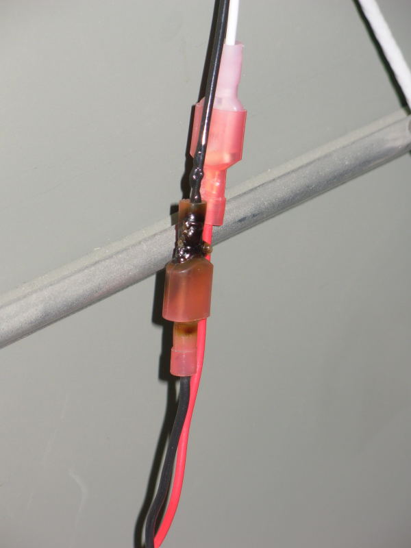
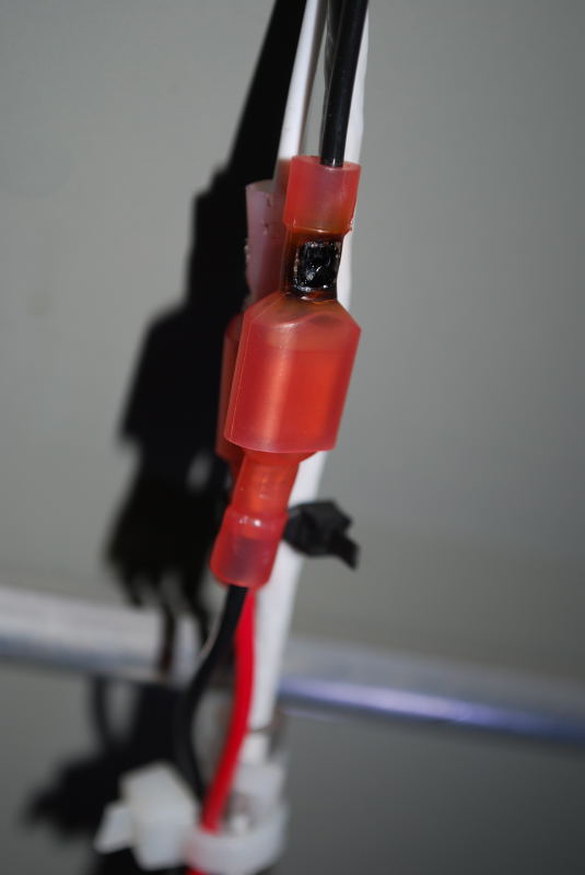
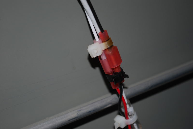
On initial failure at approx 50 hrs, I found the ground return wire for main
power plug to power supply to have overheated, melting the wire and
connector where my aircraft wiring met the factory harness pigtail (see
attached photos with "50hrs" in file name).
| Quote: | From the looks of the overheated connector for ground return wire, I assumed
I had inadvertently cut wire strands when stripping insulation for connector
|
installation, leaving not enough wire guage to carry the expected 7A
current, thus overheated the connector. So I removed the damaged wire,
replaced connector with same style (being very careful not to damage wire
strands and to get a good crimp), and tested strobes with no issues.
Everything worked fine until strobes quit firing again at about 150 hrs
total time (approx 100 hrs since first issue).
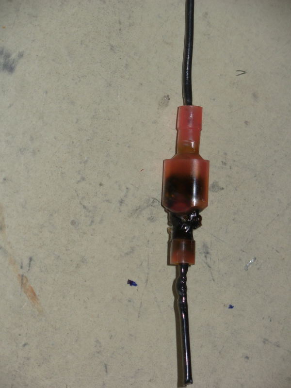
On inspection after the second failure, I found the same connector/crimp to
have visible heat damage but not to the extent of melting to an open like I
had the first time. The resistance across this heat damaged connector was
about 0.8 ohms, but not open (measured after cutting wires on either side
of the connector without disconnecting the spade terminals). See attached
pictures with "150hrs" in file name for what it looked like this second time
around.
I installed a pin/socket style AMP connector for the power and ground vice
the PIDG style connector, verified I had 12V power at the pin going into the
power supply, and verified the ground wire pin had continuity to airframe
ground (the ground return wire is connected to firewall common ground point
and appears good). But when plugged into the strobe power supply, the power
supply wouldn't fire the strobes - no charge/discharge noise and no strobe
lights.
Based on the above, I assumed the power supply must be bad and sent it to
Whelen factory repair after calling them. They said the power supply checks
out good and the connectors on the power supply look good. They are sending
it back to me with a new main power connector harness.
So, I'll reinstall when I get it back and see if I can get it to work, but
I'm still at a loss as to what went wrong with the two failures and why it
wouldn't work when I tried the AMP style connector.
I thought about trying to just ground the power supply locally, but the
installation instructions state not to do this and I don't want to make a
change that may result in strobe noise in my avionics systems. My current
installation (when strobes are working) doesn't have any strobe noise in any
of my audio/avionics systems. Grounding locally also wouldn't resolve root
cause on this since the ground return and connector should have been able to
handle the expected current load.
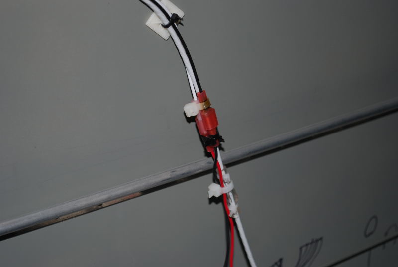
Some other pictures of power supply wiring runs and installation are at:
http://rv6aproject.ckhand.com/panelAndElectrical/electrical/electricalPg6.htm and 3rd picture down on this page: http://rv6aproject.ckhand.com/panelAndElectrical/electrical/electricalPg8.htm#photo3 Any ideas, or something I might be missing? Thanks, ChrisRV-6A, N731CK
| | - The Matronics AeroElectric-List Email Forum - | | | Use the List Feature Navigator to browse the many List utilities available such as the Email Subscriptions page, Archive Search & Download, 7-Day Browse, Chat, FAQ, Photoshare, and much more:
http://www.matronics.com/Navigator?AeroElectric-List |
|
| Description: |
|
| Filesize: |
53.92 KB |
| Viewed: |
5330 Time(s) |
|
| Description: |
|
| Filesize: |
73.06 KB |
| Viewed: |
5330 Time(s) |
|
| Description: |
|
| Filesize: |
44.05 KB |
| Viewed: |
5330 Time(s) |
|
| Description: |
|
| Filesize: |
37.88 KB |
| Viewed: |
5330 Time(s) |
|
| Description: |
|
| Filesize: |
38.5 KB |
| Viewed: |
5330 Time(s) |
|
|
|
| Back to top |
|
 |
recapen(at)earthlink.net
Guest
|
| Posted: Thu Sep 09, 2010 11:36 am Post subject: strobe power supply wiring issues |
|
|
These appear to be localized to the crimp area.


You could try solder type quick disconnects with heat-shrink tubing as the insulator to see if that truly is the issue.

--
| | - The Matronics AeroElectric-List Email Forum - | | | Use the List Feature Navigator to browse the many List utilities available such as the Email Subscriptions page, Archive Search & Download, 7-Day Browse, Chat, FAQ, Photoshare, and much more:
http://www.matronics.com/Navigator?AeroElectric-List |
|
|
|
| Back to top |
|
|
klehman(at)albedo.net
Guest
|
| Posted: Thu Sep 09, 2010 12:51 pm Post subject: strobe power supply wiring issues |
|
|
Yes I would measure the voltage on the power supply side of the

connector with everything turned on. ie verify that the power supply is

actually being powered and that the voltage stays at nominally 12 volts

while the power supply is trying to draw current. 12 volts under no load

is quite possible with a bad high resistance connection anywhere in the

circuit - but the voltage may be falling under load.

Ken


Ralph E. Capen wrote:

[quote]


 These appear to be localized to the crimp area.


 You could try solder type quick disconnects with heat-shrink tubing as the insulator to see if that truly is the issue.


 --
| | - The Matronics AeroElectric-List Email Forum - | | | Use the List Feature Navigator to browse the many List utilities available such as the Email Subscriptions page, Archive Search & Download, 7-Day Browse, Chat, FAQ, Photoshare, and much more:
http://www.matronics.com/Navigator?AeroElectric-List |
|
|
|
| Back to top |
|
|
nuckolls.bob(at)aeroelect
Guest
|
| Posted: Thu Sep 09, 2010 7:42 pm Post subject: strobe power supply wiring issues |
|
|
At 02:25 PM 9/9/2010, you wrote:
| Quote: | --> AeroElectric-List message posted by: "Ralph E. Capen" <recapen(at)earthlink.net>
These appear to be localized to the crimp area.
You could try solder type quick disconnects with heat-shrink tubing as the insulator to see if that truly is the issue. |
Agreed. Without having the carcasses to
conduct detailed autopsies, the best guess
is these are (1) non-PIDG terminals (obvious)
installed with (2)a tool that failed to produce
a gas-tight junction between wire and terminal.
An alternative or even a concurrent condition
may be that the interface between male tabe
and female fast-ons are weak. Poor alloy selection
in the fabrication of the terminal could contribute
to both failings.
See:
http://www.aeroelectric.com/articles/faston3.pdf
http://www.aeroelectric.com/articles/CrimpTools/crimptools.html
http://www.aeroelectric.com/articles/terminal.pdf
Bob . . . [quote][b]
| | - The Matronics AeroElectric-List Email Forum - | | | Use the List Feature Navigator to browse the many List utilities available such as the Email Subscriptions page, Archive Search & Download, 7-Day Browse, Chat, FAQ, Photoshare, and much more:
http://www.matronics.com/Navigator?AeroElectric-List |
|
|
|
| Back to top |
|
|
chris_hand(at)comcast.net
Guest
|
| Posted: Thu Sep 09, 2010 9:47 pm Post subject: strobe power supply wiring issues |
|
|
Thanks Bob, I'll try a different connector type  when I get the power supply back from Whelen.

 I do still have the second carcass (the less  damaged one from 150 hr point) and it's possible I might have the original  melted one if I didn't lose or toss it when I moved my plane and hangar contents  to a different airport a few months back (E16 to KRHV move in San Jose, CA  area).  I didn't cut the crimp area to look at cross-section but the  fast-on tabs looked normal and the grip strength was good when I seperated the  male and female sides after checking resistance across the connector.   I'd be happy to send you the carcass I have, or both if I can find the first  one, if you're interested in examining the crimps and connector.


 The crimp tool I used was a ratcheting AMP  ProCrimper I bought from Chief Aircraft prior to starting the electrical  system.  I used it throughout construction and have had no  problems with any other connectors.  Most of my other crimp tools (pin  & socket, and D-sub crimp tool) I bought from B&C or SteinAir so I've  got high confidence in the tools used, and I used your crimping and other  articles pretty extensively as references during my build.

 I bought most of my fast-on connectors from sources  like B&C or Stein, but towards the end of the electrical system construction  (i.e. around when I was putting the lighting systems in) I bought some  connectors from places like Home Depot and Fry's, so not sure which ones are on  the ground wire I've had problems with but that could be the issue.  Since  the second connector that burned was installed well after my plane started  flying, I'm pretty sure it's of the Home Depot / Fry's pedigree.


 Prior to starting the electrical system part of my  project, I bought and read your book and read many/most of your articles,  including the ones you linked below, before and during construction (many thanks  for your contributions and assistance to our community!).  I also had a  pretty firm electrical theory and practical experience foundation as a prior  Navy nuclear power field Electrician's Mate before reading your material.   My error may have been the Home Depot / Fry's connector source but I haven't seen anything obvious on these two particular  crimps/connectors that would lead me to believe they shouldn't have been able to  handle the expected 7A load.

 Assuming Whelen is correct that the power supply is  operating properly then clearly in both the 50 hr and 150 hr failure, that  one single crimp was inadequate, at least over time, resulting  in significant overheating.  I just don't understand why yet.


 I'll let you know when I get it hooked up and  tested again.  I appreciate your feedback.


 Chris

 [quote]   ---
| | - The Matronics AeroElectric-List Email Forum - | | | Use the List Feature Navigator to browse the many List utilities available such as the Email Subscriptions page, Archive Search & Download, 7-Day Browse, Chat, FAQ, Photoshare, and much more:
http://www.matronics.com/Navigator?AeroElectric-List |
|
|
|
| Back to top |
|
|
johnciolino(at)comcast.ne
Guest
|
| Posted: Fri Sep 10, 2010 4:09 am Post subject: strobe power supply wiring issues |
|
|
Chris,


I had a somewhat similar problem in my strobe switch, It felt very hot to

the touch although it did not burn the terminal or wire. I took  things

apart and I found that it was the wire teriminal that was getting hot (and

making the wire and switch hot).


The push on connector felt tight on the tab, but at the suggestion of our

local tech advisor, I squeezed the tab, forced on the connector (it was

really tight now) and my problem was solved.


Something to look into to.


John Ciolino

RV-8

N9394Y

---
| | - The Matronics AeroElectric-List Email Forum - | | | Use the List Feature Navigator to browse the many List utilities available such as the Email Subscriptions page, Archive Search & Download, 7-Day Browse, Chat, FAQ, Photoshare, and much more:
http://www.matronics.com/Navigator?AeroElectric-List |
|
|
|
| Back to top |
|
|
nuckolls.bob(at)aeroelect
Guest
|
| Posted: Fri Sep 10, 2010 8:22 am Post subject: strobe power supply wiring issues |
|
|
At 07:04 AM 9/10/2010, you wrote:
<johnciolino(at)comcast.net>
Chris,
I had a somewhat similar problem in my strobe switch, It felt very
hot to the touch although it did not burn the terminal or wire. I
took things apart and I found that it was the wire teriminal that
was getting hot (and making the wire and switch hot).
The push on connector felt tight on the tab, but at the suggestion of
our local tech advisor, I squeezed the tab, forced on the connector
(it was really tight now) and my problem was solved.
What brand of fast-on terminals are you using?
Something to look into to.
Many List members will recall some discussions we had
a couple years ago about switch failures . . .
http://tinyurl.com/2a2qqp
Go to the http://matronics.com/search and check
the AeroElectric archives for
carling switch failures
from the time a wire approaches one of these
switches until it winds its way off to new
adventures there's a substantial string of
metal-to-metal joints in series with the
current flow.
(1) wire to terminal grip
(2) fast-on grip to fast-on tab
(3) fast-on-tab to rivet head
(4) Rivet to saddle
(5) saddle to rocker
(6) rocker to contact
(7) contact to contact rivet
( contact rivet to fast-on tab contact rivet to fast-on tab
(9) fast-on grip to fast-on tab
(10) wire to terminal grip
In the case of Carlings, the most mechanically
fragile are 3, 4, and 8 because clamp-
up forces on the joints come against
plastic housings. The most environmentally
fragile are 5 and 7 because they cannot
strive for gas tightness.
Unfortunately, there are stresses
on the gas-tight interfaces that can degrade the
joint including process (wrong tool or
inadequate workmanship), materials (poor
choice of alloys, plating, etc), environment
vibration opens joints, moisture gets in,
etc) and even perhaps design (rare).
Once any of these joints is compromised,
it's resistance goes up, electron flow and
physical heating combined with moisture
and oxygen promote corrosion which further
degrades mechanical and electrical integrity
of the joint. It's a slay-ride down a steep
hill after that.
The most demanding circuit in the airplane
is strobes. 5-7 amps, continuous duty for
duration of flight.
When these failures are observed, there IS
an explanation that is rooted in failure to
maintain very low ohmic contact between
all the pieces and parts. Failures can
begin in any one or any one or combination
of the ten joints cited above.
Failures cited at the initial posting of this
thread have one-for-one commonality with
failures and probable causes explored in the
discussion on switch failures last year.
Bob . . .
| | - The Matronics AeroElectric-List Email Forum - | | | Use the List Feature Navigator to browse the many List utilities available such as the Email Subscriptions page, Archive Search & Download, 7-Day Browse, Chat, FAQ, Photoshare, and much more:
http://www.matronics.com/Navigator?AeroElectric-List |
|
|
|
| Back to top |
|
|
nuckolls.bob(at)aeroelect
Guest
|
| Posted: Fri Sep 10, 2010 8:36 am Post subject: strobe power supply wiring issues |
|
|
At 12:42 AM 9/10/2010, you wrote:

Thanks Bob, I'll try a different connector type when I get the power

supply back from Whelen.

I do still have the second carcass (the less damaged one from 150 hr

point) and it's possible I might have the original melted one if I

didn't lose or toss it when I moved my plane and hangar contents to a

different airport a few months back (E16 to KRHV move in San Jose, CA

area).  I didn't cut the crimp area to look at cross-section but the

fast-on tabs looked normal and the grip strength was good when I

seperated the male and female sides after checking resistance across

the connector.  I'd be happy to send you the carcass I have, or both

if I can find the first one, if you're interested in examining the

crimps and connector.


   Yes, I'd like to do that.


   Localized heating as demonstrated by color of

   the insulation tells us the failure was loss

   of gas-tightness in that area. We only need

   to deduce root cause.

The crimp tool I used was a ratcheting AMP ProCrimper I bought from

Chief Aircraft prior to starting the electrical system.  I used it

throughout construction and have had no problems with any other connectors.


   But are the fast-on terminals also made by AMP?

   The total bulk of insulator, sleeve, terminal

   material and strands of wire controls how much

   pressure the tool brings to bear on the joint.


   If you have more of the same terminals, crimp

   a couple of terminals onto a scrap of the same wire

   and send that too.


   My error may have been the Home Depot / Fry's connector source but

I haven't seen anything obvious on these two particular

crimps/connectors that would lead me to believe they shouldn't have

been able to handle the expected 7A load.


    Oops . . . current doesn't have much to

    do with joint failure . . . only the RATE

    of degradation once gas-tightness is lost.

    These kinds of failures DID NOT initiate

    in the few hours preceding events that brought

    the failures to your attention.


    Inadequate installation or improper mating

    of parts, materials and tools may have given

    you incipient failures that started marching off

    toward overt failure in the first hours of flight.

    One problem I've seen on fast-on terminals with

    indeterminate pedigree is the alloy. Some copper

    alloys are NOT capable of sustained mating forces

    over time, vibration, temperature cycles.

Assuming Whelen is correct that the power supply is operating

properly then clearly in both the 50 hr and 150 hr failure, that one

single crimp was inadequate, at least over time, resulting in

significant overheating.  I just don't understand why yet.


    Let's see if we can figure it out.

I'll let you know when I get it hooked up and tested again.  I

appreciate your feedback.

    My pleasure . . .

   Bob . . .
| | - The Matronics AeroElectric-List Email Forum - | | | Use the List Feature Navigator to browse the many List utilities available such as the Email Subscriptions page, Archive Search & Download, 7-Day Browse, Chat, FAQ, Photoshare, and much more:
http://www.matronics.com/Navigator?AeroElectric-List |
|
|
|
| Back to top |
|
|
|
|
You cannot post new topics in this forum
You cannot reply to topics in this forum
You cannot edit your posts in this forum
You cannot delete your posts in this forum
You cannot vote in polls in this forum
You cannot attach files in this forum
You can download files in this forum
|
Powered by phpBB © 2001, 2005 phpBB Group
|

