Clive J
Joined: 03 Nov 2007
Posts: 340
Location: UK
|
 Posted: Sun Dec 26, 2010 3:51 pm Post subject: Voltage Regulator Schematic for Voltage Regulator output thr Posted: Sun Dec 26, 2010 3:51 pm Post subject: Voltage Regulator Schematic for Voltage Regulator output thr |
 |
|
[img]cid:723373423(at)26122010-0D8C[/img]
From: owner-jabiruengine-list-server(at)matronics.com [mailto:owner-jabiruengine-list-server(at)matronics.com] On Behalf Of FLYaDIVE
Sent: 26 December 2010 22:49
To: jabiruengine-list(at)matronics.com
Subject: Re: JabiruEngine-List: Voltage Regulator Output
Very interesting question M Herder... Is that Mike Herder?
I use to know a Mike Herder in high school.
| Quote: |
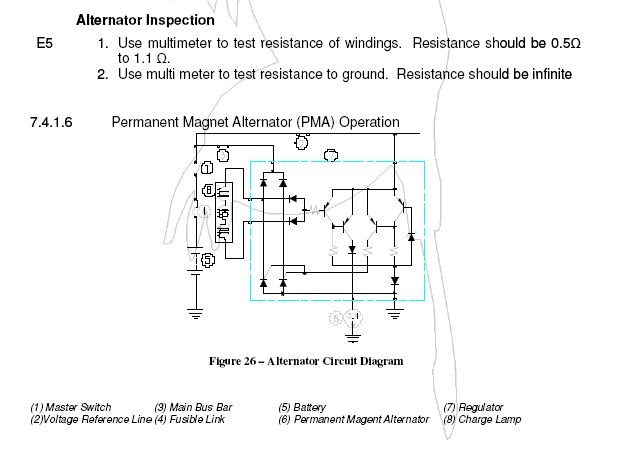
I am using a Jabiru 3300 with a permanent magnet alternator and a kubota voltage regulator. I have some questions since I don't fully understand the PM alternator output.
1) What does the voltage out of the regulator look like on an oscilloscope? Is it really pure DC or does it have some squiggles that avionics may not do so well with?
|
[Barry] - Lets back up a little to the ALTERNATOR. The out put there is pulsating DC. How much it pulsates is determined by the number and spacing of the magnets and coils on the armature.
This voltage is then sent to the Voltage Regulator (VR) a.k.a Alternator Control Unit (ACU)
http://www.bcae1.com/charging.htm
The ACU does have some very small amount of filtering to smooth out the pulsating DC / ripple, but not much.
Not much is really needed. Why? Because the BATTERY does the filtering.
You could parallel up one or some 50K uF capacitors but they will not do much. Unless you have AC noise in your system but, then you need to address more than just a capacitor at the battery. That is another question and answer.
| Quote: |
2) Jabiru suggests tying the yellow wire (senses voltage and tells whether or not the system needs charge or dumps excess to ground) and the Red wire (charges battery) as close to the positive terminal as possible. I would like to charge and sense voltage at the starter contactor for the following reason... If I have an over voltage situation, I will get an alarm from my EIS and I can simply shut off my master switch which would hopefully prevent a problem.... Take a look at my schematic and let me know what you think.
|
[Barry] - To clarify - It does NOT dump the voltage to ground. That would be a SHORT and you will be popping CB's all the time. Exactly how the voltage regulation is being done I would need a schematic of the VR. But, in most cases the Sense Voltage is used to turn ON and OFF either the FIELD - Which you do not have in a PM Alternator. Or a switching transistor to allow current flow.
" I will get an alarm from my EIS": <--- I think you meant that as a question. With the two EIS I have worked with YES you can set them up for a LOW and HIGH Limit alarm. What you do with this information is up to you and the design of your electrical system.
I would NOT want to be LIMITED to only turning on and off the Master Switch. That totally limits your ability to run off the battery. Can you post the schematic of your plane? Then I would be able to better answer what action should be taken.
If you installed a CB in series with the output of the alternator you would add protection and a means of shutting down the alternator output while allowing the Master to remain on.
Of course just like with any Split Master/Alternator you also have the addition requirement to REMEMBER to turn it ON.
| Quote: |
3) What should the voltage be at say 800 RPM, 1500 RPM and 2800 RPM?
|
[Barry] - Difficult question to answer.... TOO MANY VARIABLES. What you want to see for CHARGING is 13.8 to 14.2 VDC for a 12 volt system. Less than that and the battery will not charge. What you see is dependent on the speed of the alternator. What drives the alternator and what ratio of drive is there between the engine and the alternator. Some planes have an 11:1 drive increase. So even at idle say 650 RPM the alternator is spinning at 7150 RPM.
Measure the voltage right after start up and see what is happening.
For your other question: " also have concerns with what happens if the red and yellow are disconnected. Where would the voltage go, or would it just be an open circuit?" I would require a schematic of the VR.
Hope this helps?
Barry
| Quote: |
-------------------------------------------------------------------------
Regulator Wiring.pdf
Description:
Download
Filename: Regulator Wiring.pdf
Filesize: 10.58 KB
Downloaded: 1 Time(s)
--------------------------------------------------------------------------------
_________________
One Rivet at a Time!
Back to top
MHerder
also have concerns with what happens if the red and yellow are disconnected. Where would the voltage go, or would it just be an open circuit?
href="http://www.aeroelectric.com">www.aeroelectric.com
href="http://www.buildersbooks.com">www.buildersbooks.com
href="http://www.homebuilthelp.com">www.homebuilthelp.com
href="http://www.matronics.com/contribution">http://www.matronics.com/chref="http://www.matronics.com/Navigator?JabiruEngine-List">http://www.matronics.com/Navigator?JabiruEngine-List
href="http://forums.matronics.com">http://forums.matronics.com
|
| | - The Matronics JabiruEngine-List Email Forum - | | | Use the List Feature Navigator to browse the many List utilities available such as the Email Subscriptions page, Archive Search & Download, 7-Day Browse, Chat, FAQ, Photoshare, and much more:
http://www.matronics.com/Navigator?JabiruEngine-List |
|
| Description: |
|
| Filesize: |
38.26 KB |
| Viewed: |
2741 Time(s) |
|
|
|

