nuckolls.bob(at)aeroelect
Guest
|
 Posted: Tue Apr 17, 2012 7:35 am Post subject: The wild and wooly world of environmental compatability Posted: Tue Apr 17, 2012 7:35 am Post subject: The wild and wooly world of environmental compatability |
 |
|
At 07:02 AM 4/17/2012, you wrote:
Joe,
A larger conductor would help only if the noise you perceive is causing problems is actually an offset voltage caused by current times resistance in the wire. In other words, current pulled by one load can cause an offset voltage for the second load, and the second load can't handle the offset.
But noise is AC with a spectrum content up there at high frequencies. So when you say "noise," let's assume it is high frequency noise. If this is true, increasing conductor size only helps if it decreases its impedance, which is unlikely. You're better off rewiring such that each load has its own dedicated ground and power wires.
Henador Titzoff
Henador brings up an excellent point. The energy
sources we like to bundle together under the heading
of "antagonists" has a spectrum of qualities that include
manifestations of current, voltage, frequency, magnetic
field, electric field and even mass and velocity.
The situations we encounter most in small airplanes
are those that cause buzzes, whines, pops and other
audible effects. Then too we see changes in performance
in response to keying an on-board transmitter or flying
past a high energy RF source.
But the spectrum of potential antagonists goes lower
than audio down to DC. I related a story in the 'Connection
where a LongEz builder complained of his engine gages
shifting when the alternator was turned on/off. This was
an instance where the instruments were 'grounded' up
front at the battery . . . the sensors were 'grounded'
at the rear on the engine. The two 'grounds' were tied
together with a 10AWG piece of wire. The several hundred
millivolt shift in potential between the two grounds
as a result of alternator current upset the instruments
that were capable of displaying differences in the
tens of millivolts.
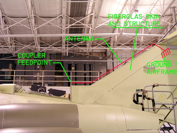
I worked what one might call the ultimate ground
loop example for RF on an airplane that featured
a HF communications antenna as part of the leading
edge structure of the vertical fin. This was a
'product upgrade' from the legacy long-wire antenna
that used to adorn the top of the airplane. Owners
of these $10 million$ airplanes really liked it
when those wires disappeared.
[img]cid:.0[/img]
Problem was, what used to be a high voltage, low
current excitation of a wire was morphed into
a low voltage, high current excitation of structure.
The 'antenna' part of the new design worked fine.
However, the 'ground' part of the system was designed
decades earlier to be strong, the right shape and
corrosion resistant. None of the various parts of
the airplane structure were attached to each other
in anticipation of carrying high current flows at
2 to 30 Mhz.
The unanticipated result gave us antagonistic
levels of RF in the 'hell hole' that far exceeded
the susceptibilities limits for several systems
that were also designed and qualified onto the
airplane decades earlier. Further, the problem
manifested only at specific frequencies that
shifted from airplane to airplane. The problem
I was tasked with involved generator regulators
that shut down when the transmitter was keyed
on specific frequencies.
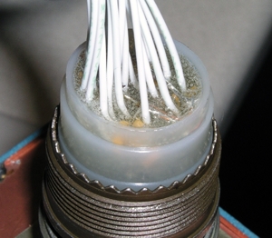
I couldn't expect all those regulators to be replaced
with modern and more robust designs. I ended up crafting a
filter-connector . . .
[img]cid:.0[/img]
[img]cid:.1[/img]
. . . which was nothing more than capacitors bypassing
certain pins to ground under the connector's back shell.
We COULD have ordered a custom connector with those
capacitors already installed but this was Dec 5th and
I was working a group of airplanes that had to be
delivered before Jan 1.
I mentioned antagonists with mass and velocity.
When designing hardware for spacecraft, the well
schooled system designer calls for radiation hardening
of the purchased products. Cosmic rays flying through the
memory cell of a computer chip can change the state
of that cell thus corrupting the data it represents
. . . or even killing the cell making it useless.
Products we delivered to the Navy had to be
qualified to work aboard aircraft carriers with
megawatt pulsed radars on board. Whole different
ball game.
Henador reminds us that artful system integration
demands a careful matching of design goals for
performance against environmental conditions that
go far beyond temperature, humidity, vibration, etc.
The short answer to your question is, "Yes. Changing
the size of the antagonist conductor will have an
influence on the level of perceived interference."
I will suggest that MOST airplanes flying today probably
have some measurable level of interference effects between
many combinations of two systems . . . they're just small
enough to be insignificant from the pilot's perspective.
As I discussed in the chapter on noise, beating the
'noise' down to acceptable (if not zero) effects
requires identification of victim, antagonist and
propagation mode. Attenuating propagation may prove
to be the elegant solution. However, eliminating the
propagation mode is the best. In the case of ground
loops, careful attention to architecture will drive
the potential for propagation via that pathway to zero.
Bob . . .
| | - The Matronics AeroElectric-List Email Forum - | | | Use the List Feature Navigator to browse the many List utilities available such as the Email Subscriptions page, Archive Search & Download, 7-Day Browse, Chat, FAQ, Photoshare, and much more:
http://www.matronics.com/Navigator?AeroElectric-List |
|
| Description: |
|
| Filesize: |
240.46 KB |
| Viewed: |
1099 Time(s) |
|
| Description: |
|
| Filesize: |
62.2 KB |
| Viewed: |
1099 Time(s) |
|
|
|

