 |
Matronics Email Lists
Web Forum Interface to the Matronics Email Lists
|
| View previous topic :: View next topic |
| Author |
Message |
paqs345(at)gmail.com
Guest
|
 Posted: Fri Aug 24, 2012 6:30 am Post subject: Upper Rudder Hinge Reinforcement. Posted: Fri Aug 24, 2012 6:30 am Post subject: Upper Rudder Hinge Reinforcement. |
 |
|
Over the years, I have watched my upper rudder hinge develop more and
more play and now finally decided to fix it. I am rather upset at the
poor design of it and how it is almost impossible to install. I dont
know if they are all the same, but mine consists of two sheet metal
tabs, about 0.04 thick, the lower one with a nutplate. This material
is too thin to be of much use as a bearing. The hole in the upper side
of the rudder is the only access and any hardware dropped in there is
impossible to get back out without major trouble.
When I tried to insert the original bolt (Im not sure how one is
supposed to do that since the hole is too small to even get a socket
in), it fell into the rudder.
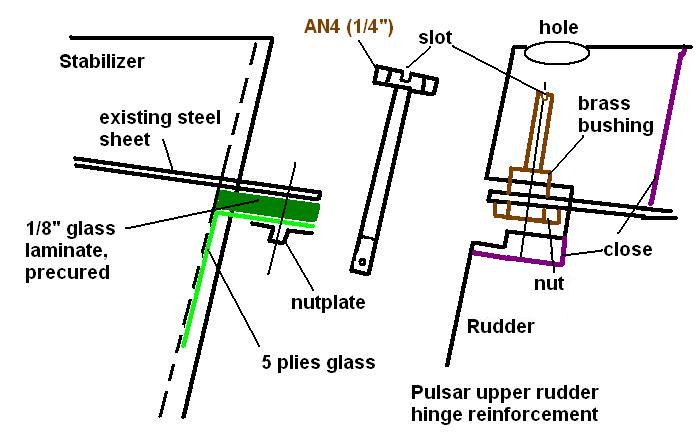
To improve the situation, I redesigned that hinge for proper function
as a bearing and easy installation. I reinforced the stabilizer side
by removing the original nut plate, bonding a 1/8 thick plate of
glass laminate underneath the metal tab and holding it in place by 5
plies glass, extending 3 down on the stabilizer. I bonded a new
nutplate (1/4) underneath this.
On the rudder, I made a bushing with a threaded portion on the lower
side and a ¼ ID for the bolt. It is long enough (upward) that the
bolt can be inserted without risk of dropping it into the rudder. The
hole in the rudder tab is enlarged to fit the bushing, which is held
in place by the nut and also bonded in. The upper end has a slot to be
able to turn it with a screwdriver during installation.
The bolt (¼, hex) is much longer now. I retained the slot in the head
to be able to use a screwdriver instead of a socket for installation.
The bolt is held by safety wire on the lower end from backing out.
This design has plenty of bearing surface and should not develop play.
It is very easy to install it.
Anyone working on building these parts should close off the rudder
structure below those holes to prevent hardware from falling in.
I have shown what I did in the attached sketch (I hope it stays attached).
Sonja
| | - The Matronics Pulsar-List Email Forum - | | | Use the List Feature Navigator to browse the many List utilities available such as the Email Subscriptions page, Archive Search & Download, 7-Day Browse, Chat, FAQ, Photoshare, and much more:
http://www.matronics.com/Navigator?Pulsar-List |
|
| Description: |
|
| Filesize: |
47.8 KB |
| Viewed: |
4428 Time(s) |
|
|
|
| Back to top |
|
 |
barryjedwards(at)lineone.
Guest
|
| Posted: Fri Aug 24, 2012 6:48 am Post subject: Upper Rudder Hinge Reinforcement. |
|
|
Hi Sonja,
I agree the original design was not very robust. Mine also has some play in it after 20 years of flying but it does not seem to have got any worse in the last 18 years! The original top bolt was a cross head machine screw in my kit which I can insert with a cross head screw driver with a dab of silicone adhesive on it to hold the two together during insertion and removal. One day Ill get around to a fix similar to yours. Thanks for the ideas.
Barry
G-XPXP 912 Tail-dragger UK 1030hrs
From: Sonja Englert (paqs345(at)gmail.com)
Sent: Friday, August 24, 2012 3:30 PM
To: pulsar-list (pulsar-list(at)matronics.com)
Subject: Upper Rudder Hinge Reinforcement.
Over the years, I have watched my upper rudder hinge develop more and
more play and now finally decided to fix it. I am rather upset at the
poor design of it and how it is almost impossible to install. I dont
know if they are all the same, but mine consists of two sheet metal
tabs, about 0.04 thick, the lower one with a nutplate. This material
is too thin to be of much use as a bearing. The hole in the upper side
of the rudder is the only access and any hardware dropped in there is
impossible to get back out without major trouble.
When I tried to insert the original bolt (Im not sure how one is
supposed to do that since the hole is too small to even get a socket
in), it fell into the rudder.
To improve the situation, I redesigned that hinge for proper function
as a bearing and easy installation. I reinforced the stabilizer side
by removing the original nut plate, bonding a 1/8 thick plate of
glass laminate underneath the metal tab and holding it in place by 5
plies glass, extending 3 down on the stabilizer. I bonded a new
nutplate (1/4) underneath this.
On the rudder, I made a bushing with a threaded portion on the lower
side and a ¼ ID for the bolt. It is long enough (upward) that the
bolt can be inserted without risk of dropping it into the rudder. The
hole in the rudder tab is enlarged to fit the bushing, which is held
in place by the nut and also bonded in. The upper end has a slot to be
able to turn it with a screwdriver during installation.
The bolt (¼, hex) is much longer now. I retained the slot in the head
to be able to use a screwdriver instead of a socket for installation.
The bolt is held by safety wire on the lower end from backing out.
This design has plenty of bearing surface and should not develop play.
It is very easy to install it.
Anyone working on building these parts should close off the rudder
structure below those holes to prevent hardware from falling in.
I have shown what I did in the attached sketch (I hope it stays attached).
Sonja
[quote][b]
| | - The Matronics Pulsar-List Email Forum - | | | Use the List Feature Navigator to browse the many List utilities available such as the Email Subscriptions page, Archive Search & Download, 7-Day Browse, Chat, FAQ, Photoshare, and much more:
http://www.matronics.com/Navigator?Pulsar-List |
|
|
|
| Back to top |
|
|
briana(at)xtra.co.nz
Guest
|
| Posted: Fri Aug 24, 2012 11:19 am Post subject: Upper Rudder Hinge Reinforcement. |
|
|
Sonja, and others,
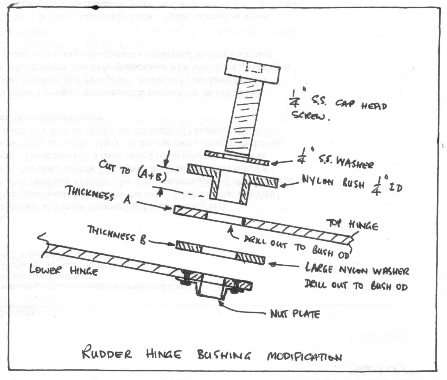
The upper rudder hinge was recognised as a potential problem a long time ago, in fact while I was still building. I closed off the rudder around and below the hinge to prevent water getting in there, and of course it also prevents any bits falling down inside the rudder.
Some of us modified the rudder hinge to include a nylon bushing. I found a source locally and supplied quite e number to other builders about that time. The hinge is still held together with a 1/4 screw. I used a SS cap screw and can check the tension from time to time using an allen key. I've not found any play in the bearing in nearly 500 hours, and only very occasionally does the cap screw need a little tweak.
I'll attach a sketch of the arrangement, but I suspect it won't travel with the e-mail. If it doesn't go I ail happily send it to anyone who asks.
Brian
On 25/08/2012, at 2:30 AM, Sonja Englert <paqs345(at)gmail.com> wrote:
| Quote: | Over the years, I have watched my upper rudder hinge develop more and
more play and now finally decided to fix it. I am rather upset at the
poor design of it and how it is almost impossible to install. I dont
know if they are all the same, but mine consists of two sheet metal
tabs, about 0.04 thick, the lower one with a nutplate. This material
is too thin to be of much use as a bearing. The hole in the upper side
of the rudder is the only access and any hardware dropped in there is
impossible to get back out without major trouble.
When I tried to insert the original bolt (Im not sure how one is
supposed to do that since the hole is too small to even get a socket
in), it fell into the rudder.
To improve the situation, I redesigned that hinge for proper function
as a bearing and easy installation. I reinforced the stabilizer side
by removing the original nut plate, bonding a 1/8 thick plate of
glass laminate underneath the metal tab and holding it in place by 5
plies glass, extending 3 down on the stabilizer. I bonded a new
nutplate (1/4) underneath this.
On the rudder, I made a bushing with a threaded portion on the lower
side and a ¼ ID for the bolt. It is long enough (upward) that the
bolt can be inserted without risk of dropping it into the rudder. The
hole in the rudder tab is enlarged to fit the bushing, which is held
in place by the nut and also bonded in. The upper end has a slot to be
able to turn it with a screwdriver during installation.
The bolt (¼, hex) is much longer now. I retained the slot in the head
to be able to use a screwdriver instead of a socket for installation.
The bolt is held by safety wire on the lower end from backing out.
This design has plenty of bearing surface and should not develop play.
It is very easy to install it.
Anyone working on building these parts should close off the rudder
structure below those holes to prevent hardware from falling in.
I have shown what I did in the attached sketch (I hope it stays attached).
Sonja
<Rudderhinge.JPG>
|
| | - The Matronics Pulsar-List Email Forum - | | | Use the List Feature Navigator to browse the many List utilities available such as the Email Subscriptions page, Archive Search & Download, 7-Day Browse, Chat, FAQ, Photoshare, and much more:
http://www.matronics.com/Navigator?Pulsar-List |
|
| Description: |
|
| Filesize: |
126.82 KB |
| Viewed: |
4427 Time(s) |
|
|
|
| Back to top |
|
|
|
|
You cannot post new topics in this forum
You cannot reply to topics in this forum
You cannot edit your posts in this forum
You cannot delete your posts in this forum
You cannot vote in polls in this forum
You cannot attach files in this forum
You can download files in this forum
|
Powered by phpBB © 2001, 2005 phpBB Group
|

