nuckolls.bob(at)aeroelect
Guest
|
 Posted: Wed Jan 30, 2013 5:03 pm Post subject: No Title Posted: Wed Jan 30, 2013 5:03 pm Post subject: No Title |
 |
|
At 03:24 PM 1/30/2013, you wrote:
| Quote: | Bob,
I'm trying to figure out my LED Nav lights and I have a couple of questions: I bought a set of wingtip LED Nav lights from a builder off of VAF who was producing them prior to you offering your LuxDrive filters. They came with 700mA LuxDrive Power Pucks. After you started offering your filters, I bought a couple of those. They came with 1000mA Power Pucks. |
Were you wanting filter boards only for your 700mA
devices? Are they the 3021 series devices with
ECB pins?
http://tinyurl.com/a4nltlv
If so, you can trade your 1000 mA filtered supplies
for filters + refund.
| Quote: | | Can I use the 1000mA models or should I reorder 700mA units? |
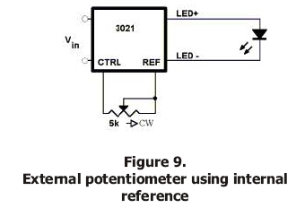
As shown on the LuxDrive data sheet, you can
'dim' the 3021 series devices by connecting
the appropriate resistor between CTRL and REF
pins.
[img]cid:.0[/img]
This adjustment sets a new operating current
that is lower than the rated current for the
device.
| Quote: |
When I received the filters, it came with a hand written sketch for a wiring diagram. I have since downloaded a newer schematic from your website. Comparing the two, I see there is a difference in them concerning pins 2 & 3. On the original hand written one, both pins are labeled “N/C”. I assume this means “Not Connected.” (?) The newer schematic shows pin 2 as 5v ref and pin 3 as “Control Dimming.” As I am not considering dimming my Nav lights, I don’t need to connect these, correct? |
You can wire a resistor (about 220 ohms I think)
between 2 and 3 on the 9-pin connector to set
your 1000 mA units to any desired lower current.
I now offer bench adjusted power supplies wherein
I attach a resistor to the bottom of the board that
produces the desired maximum current . . . this lets
me stock only one power supply (1000 mA) to service
the full range of builder needs.
In the future, I'll be re-laying the board to provide
a clearance hole to the potentiometer that comes
on the "I" devices.
| Quote: | | Also, on both drawings, pins 4 & 8 and pins 5 & 9 are common with each other. Is this for one filter to drive two different Nav lights? |
If your lamps are two strings of leds in
series where each requires 1/2 of total current,
then the extra pins enable that connection.
Let me know what works for you.
Bob . . .
| | - The Matronics AeroElectric-List Email Forum - | | | Use the List Feature Navigator to browse the many List utilities available such as the Email Subscriptions page, Archive Search & Download, 7-Day Browse, Chat, FAQ, Photoshare, and much more:
http://www.matronics.com/Navigator?AeroElectric-List |
|
| Description: |
|
| Filesize: |
27.91 KB |
| Viewed: |
1452 Time(s) |
|
|
|

