nuckolls.bob(at)aeroelect
Guest
|
 Posted: Wed Oct 09, 2013 4:47 pm Post subject: Looking for programmable electrical test box Posted: Wed Oct 09, 2013 4:47 pm Post subject: Looking for programmable electrical test box |
 |
|
At 12:30 PM 10/9/2013, you wrote:
| Quote: | I don't know what to call it, but I'm looking for a programmable electrical test box: a gizmo that I can program to apply a certain voltage or resistance or current to its connections, that I can program to vary the V, I, or R as a function of time or measured electrical parameter. So for instance I want to apply a draining current to a battery load, such that the draining current is constant (the gizmo will vary the resistance applied to achieve the constant current). The gizmo should record time, V, I, and R so I can download them via bluetooth or USB flash drive.
Does such a gizmo exist?
|
Yup. Really nice ones too . . . with prices to match.
I've used a variety of commercial load banks and have
built several more. Your choice of options is probably
budget driven so I'll suggest the po' boy's appraoch.
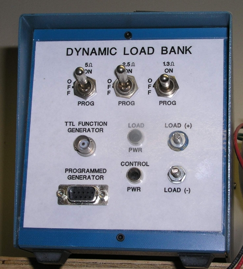
The last programmable load I built (or almost built)
looked like this
[img]cid:.0[/img]
It was a bank of 200W, 5 ohm resistors in a cabinet
with a really good fan on the back. Switches on the
front would allow me turn any one load ON, OFF, or
transfer it to a power FET that was controlled out
of a computer.
The one shown above was intended to perturb the bus
on a Horizon with pulses of various duty cycles and
amplitudes up to 40A.
This one didn't get finished because they (Beech)
abandoned the program before I got it done. But the
approach is simple. Let us suppose you want 1/2 amp
resolution at 14V. The smallest resistor in your
string would be 25 ohms. The next step is 12.5 (two
25's in parallel), the third step is 6.2 (three 20
in parallel), fourth is 3 ohms, 5th 1.5 ohms, 6th,
7th and 8th steps are .75 ohms each.
Each resistor is controlled by power N-Fet that
pulls the free end the resistor to ground. Depending
on the 8-bit word written a discrete output port,
you can command any combination of loads from about
1/2 amp to 76 amps in 1/2 amp steps.
You monitor actual current via a op-amp looking at
a shunt and diving an a/d converter. Same A/d converer
can watch voltage across the load so that you can do
either constant power or constant current operation.
A relatively simple program in Basic, C, Pascal or
even Forth can be crafted to wiggle gates on the FET
array to keep driving toward the target test value.
The last time I did this, I used Weeder Technologies
modules on the serial port of a laptop running a Basic
program. This rather pedestrian setup did a calculation/
correction cycle about 30 times a second.
You can do a Rube Goldberg lash-up in a metal box (cheap
toolbox from a garage sale using techniques that will
hang together long enough for a few tests. If you're
looking for something more robust, then a cabinet, fan,
and electronic similar to that shown in the picture
could be assembled with probably 1/2 again more$
and twice the labor.
If you elect to go this route, I can probably dig
up the BASIC software and maybe even the schematic.
Bob . . .
| | - The Matronics AeroElectric-List Email Forum - | | | Use the List Feature Navigator to browse the many List utilities available such as the Email Subscriptions page, Archive Search & Download, 7-Day Browse, Chat, FAQ, Photoshare, and much more:
http://www.matronics.com/Navigator?AeroElectric-List |
|
| Description: |
|
| Filesize: |
198.16 KB |
| Viewed: |
988 Time(s) |
|
|
|

