 |
Matronics Email Lists
Web Forum Interface to the Matronics Email Lists
|
| View previous topic :: View next topic |
| Author |
Message |
Lynn Matteson
Joined: 10 Jan 2006
Posts: 2778
Location: Grass Lake, Michigan
|
 Posted: Sat Sep 27, 2008 4:04 pm Post subject: CHT probe placement Posted: Sat Sep 27, 2008 4:04 pm Post subject: CHT probe placement |
 |
|
When I recently rebuilt my Jabiru 2200 engine, I decided it was time

to make the CHT probe move to a better location, and avoid the

dreaded spark plug gasket removal and replacement problem. I didn't

like the idea of putting the probe under a head bolt as some have

done, fearing the idea of putting 24 lbs of torque on a copper

terminal, so I followed another poster's idea and drilled and tapped

a hole in the head between, and slightly below, the spark plug

locations. Now I find that the temperature readings are quite a bit

above the reported 10 degrees or so difference (from the spark plug

locations) that I have read about for the head bolt locations. I have

looked into this and have decided that the spark plug probes (mine

anyway) position the thermocouple wire attachment point...the point

where the actual reading is made, the "business end" if you will,

(and it is NOT the area that actually touches the head)...one-half

inch above the head surface, and well into the airflow that goes past

this area. This spark plug thermocouple is further insulated by

having it *above* the spark plug gasket, making it even further from

the cylinder head, albeit by a very small amount. I believe this 1/2"

of separation from the head is enough to place the "business end" of

the t'couple in the relatively cool air passing by. I used to see

CHT's of an average of about 275° F, while I now see my CHT's read

about 350-360° F, and up to about 385° F in climb, at 1500' MSL, (at)

80° F ambient. Straight and level flight after a 5 minute settling

down period after climbout will see the 350's I mentioned. My

thermocouple attachment point...the business end...is now closer to

the head, and tucked between the head and a fin instead of sticking

up into the airflow, so I can accept the higher readings, especially

when the engine is running so strong now and climbing better than I

recall it doing before the engine breakdown. I might add that each

flight sees lower CHT's as the engine breaks in.

Any comments?


Lynn Matteson

Kitfox IV Speedster

Jabiru 2200, 562 hrs, and counting...all systems are go.
| | - The Matronics JabiruEngine-List Email Forum - | | | Use the List Feature Navigator to browse the many List utilities available such as the Email Subscriptions page, Archive Search & Download, 7-Day Browse, Chat, FAQ, Photoshare, and much more:
http://www.matronics.com/Navigator?JabiruEngine-List |
|
_________________
Lynn
Kitfox IV-Jabiru 2200
N369LM |
|
| Back to top |
|
 |
wb2ssj(at)frontiernet.net
Guest
|
| Posted: Sun Sep 28, 2008 3:39 am Post subject: CHT probe placement |
|
|
Lynn, can you post a picture of where you placed the probe.  Tex

---
| | - The Matronics JabiruEngine-List Email Forum - | | | Use the List Feature Navigator to browse the many List utilities available such as the Email Subscriptions page, Archive Search & Download, 7-Day Browse, Chat, FAQ, Photoshare, and much more:
http://www.matronics.com/Navigator?JabiruEngine-List |
|
|
|
| Back to top |
|
|
Lynn Matteson
Joined: 10 Jan 2006
Posts: 2778
Location: Grass Lake, Michigan
|
| Posted: Sun Sep 28, 2008 5:06 am Post subject: CHT probe placement |
|
|
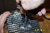
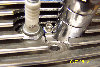
Here ya go, Tex. I had to grind a bit off the fins just above the
area, then level out the little hump, and it was clear sailing to
drill it and tap it with an 8-32 tap. I just cut the old 12mm
terminal off the t'couple lead, bared the leads a bit, shrink tubed
them right up to the bare area and inserted them into a new #8 stud
size, eye terminal. Where the leads contact each other is where the
temp reading actually takes place, so be sure to shove the bare leads
right up to the terminal before crimping. At least that's how this
anal reporter did/does it. : )
Lynn Matteson
Kitfox IV Speedster
Jabiru 2200, 562 hrs, and counting...all systems are go.
On Sep 28, 2008, at 7:38 AM, Tex Mantell wrote:
| Quote: |
<wb2ssj(at)frontiernet.net>
Lynn, can you post a picture of where you placed the probe. Tex
|
| | - The Matronics JabiruEngine-List Email Forum - | | | Use the List Feature Navigator to browse the many List utilities available such as the Email Subscriptions page, Archive Search & Download, 7-Day Browse, Chat, FAQ, Photoshare, and much more:
http://www.matronics.com/Navigator?JabiruEngine-List |
|
| Description: |
|
| Filesize: |
128.31 KB |
| Viewed: |
553 Time(s) |
|
| Description: |
|
| Filesize: |
124.52 KB |
| Viewed: |
582 Time(s) |
|
_________________
Lynn
Kitfox IV-Jabiru 2200
N369LM |
|
| Back to top |
|
|
wb2ssj(at)frontiernet.net
Guest
|
| Posted: Sun Sep 28, 2008 7:25 am Post subject: CHT probe placement |
|
|
Thanks , great pictures..

---
| | - The Matronics JabiruEngine-List Email Forum - | | | Use the List Feature Navigator to browse the many List utilities available such as the Email Subscriptions page, Archive Search & Download, 7-Day Browse, Chat, FAQ, Photoshare, and much more:
http://www.matronics.com/Navigator?JabiruEngine-List |
|
|
|
| Back to top |
|
|
jcrowder(at)lpbroadband.n
Guest
|
| Posted: Sun Sep 28, 2008 9:31 am Post subject: CHT probe placement |
|
|
Just what is a "#8 stud size, eye terminal."  A picture of this would be a

help to me.  I have the 3300 and my engine has the small holes.  I have not

measured them precisely, but as I remember a 1/8" drill will fit inside.  I

also have the Grand Rapids EIS.  I have been following your saga with great

interest.  Have you checked with GR to see if they might now offer a sensor

that might fit or be more adaptable to the hole?


As you have been experimenting with a small daylight readable screen HP

tablet computer which I have interfaced to the GR EIS.  I have programmed

Excel spreadsheet to graphically display the output from the EIS.  I will

post pictures of all of this soon.  I have also built my own cowling for my

Kitfox 5 and then more recently greatly modified the lower cowl to increase

the exit area and greatly modify the exit lip to hopefully increase the

negative air pressure to further aid cooling.  I did this without even

checking the first version after all of the comments regarding cooling.  I

will also send pictures of this soon.  My engine has yet to run, but in the

next two months I hope to have all together.


Jim Crowder


[quote] --
| | - The Matronics JabiruEngine-List Email Forum - | | | Use the List Feature Navigator to browse the many List utilities available such as the Email Subscriptions page, Archive Search & Download, 7-Day Browse, Chat, FAQ, Photoshare, and much more:
http://www.matronics.com/Navigator?JabiruEngine-List |
|
|
|
| Back to top |
|
|
Lynn Matteson
Joined: 10 Jan 2006
Posts: 2778
Location: Grass Lake, Michigan
|
| Posted: Sun Sep 28, 2008 1:36 pm Post subject: CHT probe placement |
|
|
If you go to the hardware store or auto parts store, and look for the

electrical terminals, you will see that there are red, blue and

yellow-colored terminals for wiring. The red ones are for wire sizes

22 to 18, the blue are for 16-14, I believe, and the yellows are for

wire sizes 12 to 10 as I recall. The colors are the colors of the

insulating sleeves that are fitted to the wire entry hole. That seems

to be industry-wide color coding. The other sizing is the size of the

eye, so a #8 stud size will fit over a #8 stud, or a #8 screw will go

through the hole. When I said a "#8 stud size" that means a #8 screw

will bolt the terminal to the head in this case. If you had a large

wire, like a #10 wire, you would look for a #8 (in this case) for the

hole size, but a #10 wire size. There are blade terminals, open eye

terminals, and spade terminals, and possibly others, and this refers

to the shape of the terminal where it makes a mechanical attachment

to whatever you are fastening the wire to.


In the case of your 1/8" hole in your head, that is close to the size

needed to tap it to 8-32. The 8-32 tap calls for a #29 drill for the

tap to work properly. A #29 drill measures .136", so you would want

this size hole in your head to properly tap the hole with an 8-32

tap. If your hole is only 1/8" or .125", you will need to drill to .

136" or the tap will probably break from trying to force it to go

into a hole that is too small. I have not checked with GR, preferring

to just drill to the size needed for the 8-32 tap. Remember, I had no

holes in my head, and needed to drill my own holes. I understand that

some heads are already drilled, and it was Peter Disher's post

regarding the already-drilled heads that led me to try this

thermocouple placement on my heads.


Your interfacing sounds like a great way to record data, Jim...wish I

was more computer oriented, but a pencil and paper work for me,

although I'm sure I miss a LOT of data.


Lynn Matteson

Kitfox IV Speedster

Jabiru 2200, 562 hrs, and counting...all systems are go.

On Sep 28, 2008, at 1:28 PM, Jim Crowder wrote:


[quote]

 <jcrowder(at)lpbroadband.net>


 Just what is a "#8 stud size, eye terminal."  A picture of this

 would be a

 help to me.  I have the 3300 and my engine has the small holes.  I

 have not

 measured them precisely, but as I remember a 1/8" drill will fit

 inside.  I

 also have the Grand Rapids EIS.  I have been following your saga

 with great

 interest.  Have you checked with GR to see if they might now offer

 a sensor

 that might fit or be more adaptable to the hole?


 As you have been experimenting with a small daylight readable

 screen HP

 tablet computer which I have interfaced to the GR EIS.  I have

 programmed

 Excel spreadsheet to graphically display the output from the EIS.

 I will

 post pictures of all of this soon.  I have also built my own

 cowling for my

 Kitfox 5 and then more recently greatly modified the lower cowl to

 increase

 the exit area and greatly modify the exit lip to hopefully increase

 the

 negative air pressure to further aid cooling.  I did this without even

 checking the first version after all of the comments regarding

 cooling.  I

 will also send pictures of this soon.  My engine has yet to run,

 but in the

 next two months I hope to have all together.


 Jim Crowder


> --
| | - The Matronics JabiruEngine-List Email Forum - | | | Use the List Feature Navigator to browse the many List utilities available such as the Email Subscriptions page, Archive Search & Download, 7-Day Browse, Chat, FAQ, Photoshare, and much more:
http://www.matronics.com/Navigator?JabiruEngine-List |
|
_________________
Lynn
Kitfox IV-Jabiru 2200
N369LM |
|
| Back to top |
|
|
jcrowder(at)lpbroadband.n
Guest
|
| Posted: Sun Sep 28, 2008 2:23 pm Post subject: CHT probe placement |
|
|
Lynn,

If others want, I will take this thread off line.


I already understood most of what you have related. Just what you were

referring to as the stud and the eye was not clear to me.  I am also not

clear on just what and how much remains outside of the hole.  I was thinking

you were somehow inserting the crimped portion containing the junction into

the hole.  I am now thinking you leave the crimped junction  outside of the

hole while threading the screw through the eye or ring of a terminal and

into the hole.  Will this not leave the actual sensor junction just above

the head and then therefore depending on the heat transfer from the eye and

terminal to the junction?  Does this not leave the actual terminal end and

the enclosed junction to remain in the air just above the head?  This seems

to be different than my son's bayonet sensor which as I remember inserts

into a hole in his IO360 on his RV8 which is also about to fly.  I have just

spent most of the last two days bucking rivets with him as he finish closing

his wings.  We are about to take his plane out to my hangar for a coming

first flight.


I am concerned that if I make use of the holes as you are when making my

first flights, I will not know if my CHT's readings are too high or low.

Since you are further along in this, maybe you will have established the

correct temperature thresholds.


The computer interface has taken me a long time to get working and while it

is nearly there and generally working on my bench, it is not yet complete.

It is another whole discussion which I will share either when I am just a

bit more finished, or as the group has interest.  In my post to which you

have replied, I meant to say "as you have been experimenting, I have been

experimenting."  You did seem to get my meaning, though.


Jim Crowder

Kitfox 5

3300 Jabiru Engine


[quote] --
| | - The Matronics JabiruEngine-List Email Forum - | | | Use the List Feature Navigator to browse the many List utilities available such as the Email Subscriptions page, Archive Search & Download, 7-Day Browse, Chat, FAQ, Photoshare, and much more:
http://www.matronics.com/Navigator?JabiruEngine-List |
|
|
|
| Back to top |
|
|
Lynn Matteson
Joined: 10 Jan 2006
Posts: 2778
Location: Grass Lake, Michigan
|
| Posted: Sun Sep 28, 2008 8:36 pm Post subject: CHT probe placement |
|
|
Yes, I use the hole that I drilled for the screw, and the crimped

portion lays parallel to the head and very close to the surface..as

close as a few thousandths from it....as close as the screw can clamp

it to the surface. You could also do as you say, or suggest, cut off

the eye and insert the crimped portion right into the hole if you

could come up with a suitable way to retain it there. That may be how

Peter Disher did his..see the archives from Aug 25, 2008 from this

List...he has pictures there. I just forwarded this post to you. It

*does* sound like he inserted the bare wires perhaps, right into the

hole, then ran the screw into the hole. I suppose you could tap the

hole, then maybe rout a small groove on one side of the hole in which

to insert the bare wires of the t'couple. In any case, the closer to

the head, or even right into it, the more accurate the reading. What

we are dealing with here however is "uncharted waters", in that

because no one else has done this, or reported their findings, we

don't know just what the readings should be. That's where the pucker

factor for my first flight came from.

I was quick to get the plane off the ground, thinking that I'd better

get it up there and get cooler air flowing over the engine.  I was

thinking that my seemingly elevated temps were the result of the

newly honed cylinders and new piston rings causing high friction, but

it was the more accurate readings of the t'couple probe placement

that revealed the higher temps. So what IS the proper temp, now that

we have the more accurate readings....beats me!!  Maybe Jabiru knows.

For me, I just tried to keep it below their posted max of 392° F, but

it did go over that once, on the initial startup, running it on the

ground. That's why I quickly got it into the air, and that act almost

bit me in the butt. The tight engine wasn't climbing very well, so I

kept it above tree level, climbing slightly and getting it turned

around and landed. When I realized that the engine didn't feel any

hotter than before, I started to realize that the feel of the engine

was the same as before, but the readings were higher because the

probe was no longer 1/2" away from the head, up into the airstream,

being cooled and giving lower but inaccurate readings of the actual

temp of the head. This is all fine and good if we all do it just the

way Jabiru does it, with the spark plug probes. So I unpuckered, and

began to accept that I would now be seeing 350-380° F as the

norm....my norm, instead of the 275° of before. I guess this is where

the "experimenting" part comes in. : )


I flew to an airport about 40 miles away today, and my head temps

were running about 358 for the most part, and I've accepted that as

my new norm. It comforts me to know that I haven't changed anything

relating to airflow, so I'm accepting the higher readings as being

"normal."


I also wish that Jabiru would give us a socket for a bayonet sensor,

or at least report what such a probe placement would reveal in the

way of temps.


Yes, I kind of read between the lines on your experimenting, and

please do keep *us all* posted on your progress....I'm sure that this

is the kind of thing that this List is meant to do...inform and share

all aspects of Jabiru engine-related experimentation. At least that's

the way I read it.

Lynn Matteson

Kitfox IV Speedster

Jabiru 2200, 562 hrs, and counting...all systems are go, or nearly so...

On Sep 28, 2008, at 6:22 PM, Jim Crowder wrote:


[quote]

 <jcrowder(at)lpbroadband.net>


 Lynn,

 If others want, I will take this thread off line.


 I already understood most of what you have related. Just what you were

 referring to as the stud and the eye was not clear to me.  I am

 also not

 clear on just what and how much remains outside of the hole.  I was

 thinking

 you were somehow inserting the crimped portion containing the

 junction into

 the hole.  I am now thinking you leave the crimped junction

 outside of the

 hole while threading the screw through the eye or ring of a

 terminal and

 into the hole.  Will this not leave the actual sensor junction just

 above

 the head and then therefore depending on the heat transfer from the

 eye and

 terminal to the junction?  Does this not leave the actual terminal

 end and

 the enclosed junction to remain in the air just above the head?

 This seems

 to be different than my son's bayonet sensor which as I remember

 inserts

 into a hole in his IO360 on his RV8 which is also about to fly.  I

 have just

 spent most of the last two days bucking rivets with him as he

 finish closing

 his wings.  We are about to take his plane out to my hangar for a

 coming

 first flight.


 I am concerned that if I make use of the holes as you are when

 making my

 first flights, I will not know if my CHT's readings are too high or

 low.

 Since you are further along in this, maybe you will have

 established the

 correct temperature thresholds.


 The computer interface has taken me a long time to get working and

 while it

 is nearly there and generally working on my bench, it is not yet

 complete.

 It is another whole discussion which I will share either when I am

 just a

 bit more finished, or as the group has interest.  In my post to

 which you

 have replied, I meant to say "as you have been experimenting, I

 have been

 experimenting."  You did seem to get my meaning, though.


 Jim Crowder

 Kitfox 5

 3300 Jabiru Engine


> --
| | - The Matronics JabiruEngine-List Email Forum - | | | Use the List Feature Navigator to browse the many List utilities available such as the Email Subscriptions page, Archive Search & Download, 7-Day Browse, Chat, FAQ, Photoshare, and much more:
http://www.matronics.com/Navigator?JabiruEngine-List |
|
_________________
Lynn
Kitfox IV-Jabiru 2200
N369LM |
|
| Back to top |
|
|
craig(at)craigandjean.com
Guest
|
| Posted: Sun Sep 28, 2008 8:45 pm Post subject: CHT probe placement |
|
|
Temporarily install a thermocouple under the plug and in your new hole. That

will allow you to build a conversion chart.


-- Craig
| | - The Matronics JabiruEngine-List Email Forum - | | | Use the List Feature Navigator to browse the many List utilities available such as the Email Subscriptions page, Archive Search & Download, 7-Day Browse, Chat, FAQ, Photoshare, and much more:
http://www.matronics.com/Navigator?JabiruEngine-List |
|
|
|
| Back to top |
|
|
jcrowder(at)lpbroadband.n
Guest
|
| Posted: Sun Sep 28, 2008 10:22 pm Post subject: CHT probe placement |
|
|
Lynn,

I now understand.  Unless I am confident of where I am going with this, I am

reluctant to drill into my head as Peter did.  Has Peter reported the

temperatures he is getting, or is he not flying yet?  I should think your

temperatures would be similar to what others get with the rings under the

head bolts if they allow the sensor to lie flat upon the head.  There is a

paste that could also be placed under the terminal that enhances heat

conduction.  It is used with heat sinks, etc.  I do not know the operating

temperature of it.  I just looked at my temperature probes and I could cut

the end portion of the rings so as to remove a horseshoe shaped portion of

the ring and leave a spade like flat remainder that I could easily drill for

a #8 screw. That way I believe I would not need to remove the old terminal

and still get the same result.  Did you consider that or were your sensors

different?


I have copied my Excel display screen to a Word document and I will attempt

to post by attaching hereto.  On the display you will see the graph with

inserted values except for CHT which were actual values from my GR

instrument with the sensors attached and I had heated them with a heat gun

while held in a cluster by hand.  When the snapshot was taken they had

cooled down to below normal operating temperature.  They are all displayed

in red as I had set the program to display red when above or below the safe

operational range.  If above safe temperature they would also display red.

Yellow is for near high or low and green is for the optimum range.  It is

really fun to watch them change colors and move up and down as I apply heat

or remove it.  These ranges are set by typing the various numbers into the

spreadsheet at setup.  I do not have rate of cooling programmed yet. My

Tablet Computer is very flat and has only a 12" diag. display.  In use I

will mount it on my instrument panel and the display I have attached will

take up one half of the display with Vista GPS driven moving chart taking up

the other half.  I have tried this in my car and boat and it works nicely.

Note the fuel flow is red as such a flow would indicate a problem.  The same

for the cooling rate which is not now truly functional yet.  This should

work on any laptop with my software and interface.  I have spent way too

much time on this.


I will be interested to see if the attached file goes through.  If not I

will send it directly to you.


Jim Crowder

Kitfox 5

Jabiru 3300 engine


[quote] --
| | - The Matronics JabiruEngine-List Email Forum - | | | Use the List Feature Navigator to browse the many List utilities available such as the Email Subscriptions page, Archive Search & Download, 7-Day Browse, Chat, FAQ, Photoshare, and much more:
http://www.matronics.com/Navigator?JabiruEngine-List |
|
| Description: |
|

Download |
| Filename: |
Excel_Display.doc |
| Filesize: |
1.54 MB |
| Downloaded: |
452 Time(s) |
|
|
| Back to top |
|
|
jcrowder(at)lpbroadband.n
Guest
|
| Posted: Sun Sep 28, 2008 10:41 pm Post subject: CHT probe placement |
|
|
For myself, I thought of that, but it would add another issue to a first

flight and my displays would be confusing with incorrect labeling.  It might

be a thing to do later.  Anyway, I am hoping someone else will have done

that for me. ;>)

Jim Crowder


[quote] --
| | - The Matronics JabiruEngine-List Email Forum - | | | Use the List Feature Navigator to browse the many List utilities available such as the Email Subscriptions page, Archive Search & Download, 7-Day Browse, Chat, FAQ, Photoshare, and much more:
http://www.matronics.com/Navigator?JabiruEngine-List |
|
|
|
| Back to top |
|
|
pjdisher(at)bigpond.com
Guest
|
| Posted: Sun Sep 28, 2008 11:41 pm Post subject: CHT probe placement |
|
|
Jim, My temperatures are now 1-296F. 2-328, 3-378, 4-348, 5-360, 6-332F

These temps are taxing only, I haven't flowen as yet, still waiting

inspection.

I still have my probes as they are in my post of the 25 aug photos attached.

I had an earlier problem with No 5 at 420F and found that the rubber pipe

joiner on the intake pipe was loose and leaking air.

I do think that the temps might record a little higher where I put them.

I did also remove the "V" plates from on top of cylinder and put them

underneath.


Pete Disher

---
| | - The Matronics JabiruEngine-List Email Forum - | | | Use the List Feature Navigator to browse the many List utilities available such as the Email Subscriptions page, Archive Search & Download, 7-Day Browse, Chat, FAQ, Photoshare, and much more:
http://www.matronics.com/Navigator?JabiruEngine-List |
|
|
|
| Back to top |
|
|
Terry Phillips

Joined: 11 Jan 2006
Posts: 346
Location: Corvallis, MT
|
| Posted: Mon Sep 29, 2008 3:18 am Post subject: Re: CHT probe placement |
|
|
Jim


From your post I can see that you are well along in developing your own EFIS data acquisition software. Even so, you may want to take a look at Waiter's program:


http://www.iflyez.com/EFISRecorder.shtml


It has been available for several years and is frequently updated. Best of all, it s free.


I am planning to use it to record all EFIS and EIS data when I get to the flight test stage.


Terry
| | - The Matronics JabiruEngine-List Email Forum - | | | Use the List Feature Navigator to browse the many List utilities available such as the Email Subscriptions page, Archive Search & Download, 7-Day Browse, Chat, FAQ, Photoshare, and much more:
http://www.matronics.com/Navigator?JabiruEngine-List |
|
_________________
Terry Phillips
Corvallis, MT
ttp44<at>rkymtn.net
Zenith 601XL/Jab 3300 slow build kit - Tail feathers done; working on the wings. |
|
| Back to top |
|
|
mefriesen(at)mts.net
Guest
|
| Posted: Mon Sep 29, 2008 4:37 am Post subject: CHT probe placement |
|
|
Just a thought Lynn. Do you still have a spark plug ring thermocouple that

you could place on the same cylinder as the newly placed thermocouple?

Reading both temps at the same time should give a good comparison.


Mervin Friesen

Sonex 122  Jab 2200


--
| | - The Matronics JabiruEngine-List Email Forum - | | | Use the List Feature Navigator to browse the many List utilities available such as the Email Subscriptions page, Archive Search & Download, 7-Day Browse, Chat, FAQ, Photoshare, and much more:
http://www.matronics.com/Navigator?JabiruEngine-List |
|
|
|
| Back to top |
|
|
Lynn Matteson
Joined: 10 Jan 2006
Posts: 2778
Location: Grass Lake, Michigan
|
| Posted: Mon Sep 29, 2008 4:52 am Post subject: CHT probe placement |
|
|
Amazingly simple, but great idea, Craig...if I hadn't already
committed to the location I have now, I'd do it. Somebody else do it
and let me and the others know. Jim?
Lynn Matteson
Kitfox IV Speedster
Jabiru 2200, 562 hrs, and counting...all systems are go, or nearly so...
On Sep 29, 2008, at 12:44 AM, Craig Payne wrote:
| Quote: |
<craig(at)craigandjean.com>
Temporarily install a thermocouple under the plug and in your new
hole. That
will allow you to build a conversion chart.
-- Craig
|
| | - The Matronics JabiruEngine-List Email Forum - | | | Use the List Feature Navigator to browse the many List utilities available such as the Email Subscriptions page, Archive Search & Download, 7-Day Browse, Chat, FAQ, Photoshare, and much more:
http://www.matronics.com/Navigator?JabiruEngine-List |
|
_________________
Lynn
Kitfox IV-Jabiru 2200
N369LM |
|
| Back to top |
|
|
Lynn Matteson
Joined: 10 Jan 2006
Posts: 2778
Location: Grass Lake, Michigan
|
| Posted: Mon Sep 29, 2008 5:17 am Post subject: CHT probe placement |
|
|
I haven't seen a post by Peter since the Aug 25 one....did you get

his post that I forwarded to you, Jim?

I think I would be reluctant to change anything right now too, if I

were you, Jim, being as how you are still under warranty. Being as

how I am way over warranty, and the factory doesn't seem to give two

hoots about even seeing my recent gear breakage (other than the

picture that Pete forwarded to them), or trying to determine why it

would break, I think they would take delight in voiding your warranty

at the mere mention of doing anything other than what is cast in

stone....sorry, I'm not the biggest fan of the Jabiru corp at this

moment.


Cutting the present terminal like you describe sounds like a good way

to go. I didn't consider that because I could see some rust on the

"iron" wire....the probes are two dissimilar wires, iron and

constantan....where the insulation was frayed, and wanted to scrape

the rust clean and re-insulate, so I opted for the new terminal.

Being that your terminals are probably new and ok, I'd do like you

suggested and cut them when you do decide to go ahead and change them.


I got the attachment, but all I see when opening it is:   "EMBED

PBrush"  (without the quotes) within a rectangular border, and

nothing else. Of course I'm on an eMac so my world of computers

differs from yours, I'm sure. I cannot see some of the stuff that the

IBM world sees.

Lynn Matteson

Kitfox IV Speedster

Jabiru 2200, 562 hrs, and counting...all systems are go, or nearly so...

On Sep 29, 2008, at 2:19 AM, Jim Crowder wrote:


[quote] Lynn,

 I now understand.  Unless I am confident of where I am going with

 this, I am

 reluctant to drill into my head as Peter did.  Has Peter reported the

 temperatures he is getting, or is he not flying yet?  I should

 think your

 temperatures would be similar to what others get with the rings

 under the

 head bolts if they allow the sensor to lie flat upon the head.

 There is a

 paste that could also be placed under the terminal that enhances heat

 conduction.  It is used with heat sinks, etc.  I do not know the

 operating

 temperature of it.  I just looked at my temperature probes and I

 could cut

 the end portion of the rings so as to remove a horseshoe shaped

 portion of

 the ring and leave a spade like flat remainder that I could easily

 drill for

 a #8 screw. That way I believe I would not need to remove the old

 terminal

 and still get the same result.  Did you consider that or were your

 sensors

 different?


 I have copied my Excel display screen to a Word document and I will

 attempt

 to post by attaching hereto.  On the display you will see the graph

 with

 inserted values except for CHT which were actual values from my GR

 instrument with the sensors attached and I had heated them with a

 heat gun

 while held in a cluster by hand.  When the snapshot was taken they had

 cooled down to below normal operating temperature.  They are all

 displayed

 in red as I had set the program to display red when above or below

 the safe

 operational range.  If above safe temperature they would also

 display red.

 Yellow is for near high or low and green is for the optimum range.

 It is

 really fun to watch them change colors and move up and down as I

 apply heat

 or remove it.  These ranges are set by typing the various numbers

 into the

 spreadsheet at setup.  I do not have rate of cooling programmed

 yet. My

 Tablet Computer is very flat and has only a 12" diag. display.  In

 use I

 will mount it on my instrument panel and the display I have

 attached will

 take up one half of the display with Vista GPS driven moving chart

 taking up

 the other half.  I have tried this in my car and boat and it works

 nicely.

 Note the fuel flow is red as such a flow would indicate a problem.

 The same

 for the cooling rate which is not now truly functional yet.  This

 should

 work on any laptop with my software and interface.  I have spent

 way too

 much time on this.


 I will be interested to see if the attached file goes through.  If

 not I

 will send it directly to you.


 Jim Crowder

 Kitfox 5

 Jabiru 3300 engine


> --
| | - The Matronics JabiruEngine-List Email Forum - | | | Use the List Feature Navigator to browse the many List utilities available such as the Email Subscriptions page, Archive Search & Download, 7-Day Browse, Chat, FAQ, Photoshare, and much more:
http://www.matronics.com/Navigator?JabiruEngine-List |
|
_________________
Lynn
Kitfox IV-Jabiru 2200
N369LM |
|
| Back to top |
|
|
Lynn Matteson
Joined: 10 Jan 2006
Posts: 2778
Location: Grass Lake, Michigan
|
| Posted: Mon Sep 29, 2008 5:46 am Post subject: CHT probe placement |
|
|
Nope, I replaced all spark plug probes with the #8 electrical ring

terminal, and I don't want to change back now. I'm pretty confident

that the readings I'm getting now are all ok, just nothing to compare

them to at the present. The engine runs fine, climbs well, and

doesn't seem any hotter than before after shut-down, so I'm playing

it by the seat of my pants and assuming everything to be ok.


Just as an aside, I used to install thermocouples on test cars that

we would run in the wind tunnel at Chrysler Proving Grounds. They

were having problems attaching the probes onto exhaust manifolds.

They tried brazing them on, and the braze would pop off...they might

not have gotten a clean job....so they would braze and use high temp

tape to hold them in place. They weren't getting the numbers they

expected, and would discover that the probe wasn't touching the

manifold any longer.

The I started to experiment with a TIG welder, and found that I could

melt a small puddle on the manifold and quickly insert the probe

wires into the molten cast iron and hold it until the puddle

solidified. We never had another issue with them coming off. I also

found the same method to work where they were trying to read the

temperature of the back of the aluminum bell housing on an automatic

transmission. (They were concerned with reducing the heat coming

through the floor mats) Like the manifolds, the t'couples would fall

off when merely taped into position, so I fired up the TIG and melted

a small puddle right where they wanted it, and stuck the probe into

it. Again, the probes never came off.

These probes were iron-constantan, or J type, and chromel-alumel, or

K type. The J's work best up to about 600° F as I recall, and the K's

are best at 600 and above. Our plug/CHT probes are the J type and the

EGT probes are K type.


Lynn Matteson

Kitfox IV Speedster

Jabiru 2200, 562 hrs, and counting...all systems are go, or nearly so...

On Sep 29, 2008, at 8:36 AM, Mervin Friesen wrote:


[quote]

 <mefriesen(at)mts.net>


 Just a thought Lynn. Do you still have a spark plug ring

 thermocouple that

 you could place on the same cylinder as the newly placed thermocouple?

 Reading both temps at the same time should give a good comparison.


 Mervin Friesen

 Sonex 122  Jab 2200


 --
| | - The Matronics JabiruEngine-List Email Forum - | | | Use the List Feature Navigator to browse the many List utilities available such as the Email Subscriptions page, Archive Search & Download, 7-Day Browse, Chat, FAQ, Photoshare, and much more:
http://www.matronics.com/Navigator?JabiruEngine-List |
|
_________________
Lynn
Kitfox IV-Jabiru 2200
N369LM |
|
| Back to top |
|
|
jcrowder(at)lpbroadband.n
Guest
|
| Posted: Mon Sep 29, 2008 6:25 am Post subject: CHT probe placement |
|
|
Lynn,

Sorry it did not display.  It did display on mine when I received it back.

I think it is a Mac related problem--different systems.  I will try

something else soon and send it to you directly.  I'm about to head out to

my hangar to refit the cowl I just modified again. Then I will move on to

the engine install.  Currently it's just hanging there with not much else

done.


Jim Crowder


[quote] --
| | - The Matronics JabiruEngine-List Email Forum - | | | Use the List Feature Navigator to browse the many List utilities available such as the Email Subscriptions page, Archive Search & Download, 7-Day Browse, Chat, FAQ, Photoshare, and much more:
http://www.matronics.com/Navigator?JabiruEngine-List |
|
|
|
| Back to top |
|
|
jcrowder(at)lpbroadband.n
Guest
|
| Posted: Mon Sep 29, 2008 6:26 am Post subject: CHT probe placement |
|
|
Pete,

Thanks for your reply.  Please keep me updated.


Jim Crowder


[quote] --
| | - The Matronics JabiruEngine-List Email Forum - | | | Use the List Feature Navigator to browse the many List utilities available such as the Email Subscriptions page, Archive Search & Download, 7-Day Browse, Chat, FAQ, Photoshare, and much more:
http://www.matronics.com/Navigator?JabiruEngine-List |
|
|
|
| Back to top |
|
|
jcrowder(at)lpbroadband.n
Guest
|
| Posted: Mon Sep 29, 2008 6:35 am Post subject: CHT probe placement |
|
|
Lynn,

I have converted the screen shot to an Adobe PDF document and attached it

here.  That should work better for everyone.

Jim Crowder


[quote] --
| | - The Matronics JabiruEngine-List Email Forum - | | | Use the List Feature Navigator to browse the many List utilities available such as the Email Subscriptions page, Archive Search & Download, 7-Day Browse, Chat, FAQ, Photoshare, and much more:
http://www.matronics.com/Navigator?JabiruEngine-List |
|
| Description: |
|
Download |
| Filename: |
Excel_Display.pdf |
| Filesize: |
25.34 KB |
| Downloaded: |
476 Time(s) |
|
|
| Back to top |
|
|
|
|
You cannot post new topics in this forum
You cannot reply to topics in this forum
You cannot edit your posts in this forum
You cannot delete your posts in this forum
You cannot vote in polls in this forum
You cannot attach files in this forum
You can download files in this forum
|
Powered by phpBB © 2001, 2005 phpBB Group
|

