 |
Matronics Email Lists
Web Forum Interface to the Matronics Email Lists
|
| View previous topic :: View next topic |
| Author |
Message |
jay(at)horriblehyde.com
Guest
|
 Posted: Wed Sep 02, 2009 5:48 am Post subject: Alternator connections Posted: Wed Sep 02, 2009 5:48 am Post subject: Alternator connections |
 |
|
Hi there,
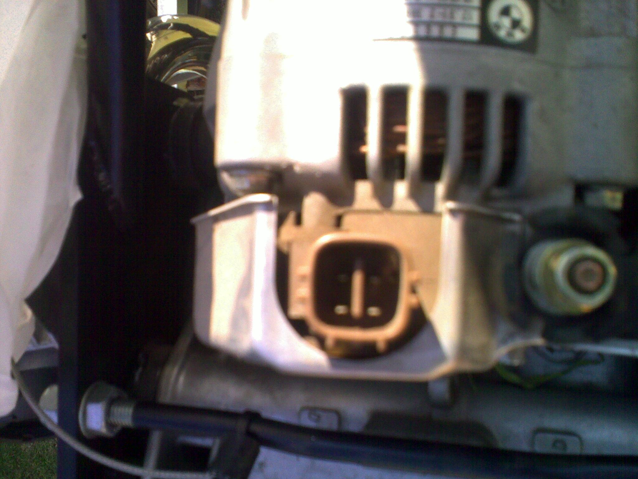
I am trying to connect a Nippon Denso alternator into a Z scheme and am confused as to the connections. There are 4 small pins in a plastic housing and it is these whose function/ connection I cannot deduce. To me there should be only 1 or 2 pins for positive and negative of the field, or just positive. The photo (although blurred) shows the pin arrangement of two pairs of pins separated by a plastic shield. Can anyone cast any light on how to connect these?
Thanks
Jay
| | - The Matronics AeroElectric-List Email Forum - | | | Use the List Feature Navigator to browse the many List utilities available such as the Email Subscriptions page, Archive Search & Download, 7-Day Browse, Chat, FAQ, Photoshare, and much more:
http://www.matronics.com/Navigator?AeroElectric-List |
|
| Description: |
|
| Filesize: |
322.26 KB |
| Viewed: |
4266 Time(s) |
|
|
|
| Back to top |
|
 |
nuckolls.bob(at)aeroelect
Guest
|
| Posted: Wed Sep 02, 2009 7:14 am Post subject: Alternator connections |
|
|
At 08:30 AM 9/2/2009, you wrote:
| Quote: | Hi there,
I am trying to connect a Nippon Denso alternator into a Z scheme and am confused as to the connections. There are 4 small pins in a plastic housing and it is these whose function/ connection I cannot deduce. To me there should be only 1 or 2 pins for positive and negative of the field, or just positive. The photo (although blurred) shows the pin arrangement of two pairs of pins separated by a plastic shield. Can anyone cast any light on how to connect these?
Thanks
Jay |
What's the part number or better yet, the Lester number
of your particular alternator. You can get a pinout
at:
http://www.quality-built.com/catalog.htm
Enter make, model of car that the alternator is used
on or . . .
go to the "Cross Reference" tab of the above
link and enter the OEM or Lester number.
Step though the various photo views of the
particular alternator and I think you'll find
that one of the photos is a pinout diagram.
Having said that, you probably wont find a
connection to your alternator's field terminals.
The vast majority of alternators in the automotive
wild have built in regulators.
Bob . . .
---------------------------------------
( . . . a long habit of not thinking )
( a thing wrong, gives it a superficial )
( appearance of being right . . . )
( )
( -Thomas Paine 1776- )
---------------------------------------
[quote][b]
| | - The Matronics AeroElectric-List Email Forum - | | | Use the List Feature Navigator to browse the many List utilities available such as the Email Subscriptions page, Archive Search & Download, 7-Day Browse, Chat, FAQ, Photoshare, and much more:
http://www.matronics.com/Navigator?AeroElectric-List |
|
|
|
| Back to top |
|
|
jay(at)horriblehyde.com
Guest
|
| Posted: Thu Sep 03, 2009 2:56 am Post subject: Alternator connections |
|
|
Thanks Bob,
I tried that and it gave me a few clues but I am not sure what the lester number is. I tried all of the numbers on the nameplate and came up with a few hits but none that worked. Trouble with specifying the make model etc is that it is a motorbike engine and they don’t list those.
So, back to basics, there are 4 terminals, and a small diagram that indicate that 2 of them are ‘IG’ and ‘L’. >From looking at some of the alternator diagrams at the link you gave I found that there are the following possible connections, Ignition, Light and Sense. This is where I get stuck, I am expecting Field and Earth/ Ground.
What is Ignition and Sense for- or how should they be used? And how is the Light circuit wired? My idea of a light warning circuit is that one side of the light is connected (via a switch, etc) to the battery positive terminal and the other side to the 12-14V out from the alternator. If either the battery voltage or the alternator voltage drops the light goes on?
The Ignition cct is sort of the field winding in that it requires 12V in?
Have no idea what the Sense cct might be; any ideas?
Thanks
Jay
~~~~~~~~~~~~~~~~~~~~~~~~~~~~~~~~~~~~~~~~~~~~~~
From: owner-aeroelectric-list-server(at)matronics.com [mailto:owner-aeroelectric-list-server(at)matronics.com] On Behalf Of Robert L. Nuckolls, III
Sent: 02 September 2009 05:12 PM
To: aeroelectric-list(at)matronics.com
Subject: Re: AeroElectric-List: Alternator connections
At 08:30 AM 9/2/2009, you wrote:
Hi there,
I am trying to connect a Nippon Denso alternator into a Z scheme and am confused as to the connections. There are 4 small pins in a plastic housing and it is these whose function/ connection I cannot deduce. To me there should be only 1 or 2 pins for positive and negative of the field, or just positive. The photo (although blurred) shows the pin arrangement of two pairs of pins separated by a plastic shield. Can anyone cast any light on how to connect these?
Thanks
Jay
What's the part number or better yet, the Lester number
of your particular alternator. You can get a pinout
at:
http://www.quality-built.com/catalog.htm
Enter make, model of car that the alternator is used
on or . . .
go to the "Cross Reference" tab of the above
link and enter the OEM or Lester number.
Step though the various photo views of the
particular alternator and I think you'll find
that one of the photos is a pinout diagram.
Having said that, you probably wont find a
connection to your alternator's field terminals.
The vast majority of alternators in the automotive
wild have built in regulators.
Bob . . .
---------------------------------------
( . . . a long habit of not thinking )
( a thing wrong, gives it a superficial )
( appearance of being right . . . )
( )
( -Thomas Paine 1776- )
--------------------------------------- | Quote: | | http://www.matronics.com/Navigator?AeroElectric-List |
0123456789
[quote][b]
| | - The Matronics AeroElectric-List Email Forum - | | | Use the List Feature Navigator to browse the many List utilities available such as the Email Subscriptions page, Archive Search & Download, 7-Day Browse, Chat, FAQ, Photoshare, and much more:
http://www.matronics.com/Navigator?AeroElectric-List |
|
|
|
| Back to top |
|
|
nuckolls.bob(at)aeroelect
Guest
|
| Posted: Thu Sep 03, 2009 5:26 am Post subject: Alternator connections |
|
|
At 05:54 AM 9/3/2009, you wrote:
| Quote: | Thanks Bob,
So, back to basics, there are 4 terminals, and a small diagram that indicate that 2 of them are IG and L. >From looking at some of the alternator diagrams at the link you gave I found that there are the following possible connections, Ignition, Light and Sense. This is where I get stuck, I am expecting Field and Earth/ Ground. |
Well, if they are marked, then you wouldn't get any
different information from the catalogs that only
go telling you what the labels are.
IG is the alternator ON-OFF control lead and is the
lead depicted on
http://www.aeroelectric.com/PPS/Adobe_Architecture_Pdfs/Z24-Interim.pdf
for controlling the alternator. I note that there
is an error on that drawing that calls the input
terminal "F" when indeed, it is "IGN".
"L" is for a warning light that can be ignored.
The best guess for "sense" is that it's a voltage
control input lead for the regulator.
| Quote: |
What is Ignition and Sense for- or how should they be used? And how is the Light circuit wired? My idea of a light warning circuit is that one side of the light is connected (via a switch, etc) to the battery positive terminal and the other side to the 12-14V out from the alternator. If either the battery voltage or the alternator voltage drops the light goes on?
The Ignition cct is sort of the field winding in that it requires 12V in?
Have no idea what the Sense cct might be; any ideas? |
If it's off a motorcycle, get the wiring
diagram for the motorcycle and duplicate that.
Otherwise, consider disassembling the alternator
to remove the built in regulator and bring the
field leads out so you can use an external
regulator.
Bob . . .
---------------------------------------
( . . . a long habit of not thinking )
( a thing wrong, gives it a superficial )
( appearance of being right . . . )
( )
( -Thomas Paine 1776- )
---------------------------------------
[quote][b]
| | - The Matronics AeroElectric-List Email Forum - | | | Use the List Feature Navigator to browse the many List utilities available such as the Email Subscriptions page, Archive Search & Download, 7-Day Browse, Chat, FAQ, Photoshare, and much more:
http://www.matronics.com/Navigator?AeroElectric-List |
|
|
|
| Back to top |
|
|
ianxbrown
Joined: 16 May 2009
Posts: 80
|
| Posted: Thu Sep 03, 2009 5:52 am Post subject: Alternator connections |
|
|
On my Nippon Denso internally regulated alternator, there are essentially four connectors, two of which are in a "T" arrangement.
1. The big battery terminal.
2. The IG terminal which is 12v from the battery through the alternator switch on the panel then to the IG terminal.
3. The L (lamp) switch which is grounded in the alternator when the alternator is not charging. A lamp connected from 12V through the lamp to L would be off in a normally running engine, and on if the alternator was not charging.
4. The ground is through the body of the alternator, and depends on the grounding strap from the engine to the firewall.
Ian Brown,
Bromont
Quebec
C-GOHM RV-9A flying
On Thu, 2009-09-03 at 12:54 +0200, Jay Hyde wrote: | Quote: | Thanks Bob,
I tried that and it gave me a few clues but I am not sure what the lester number is. I tried all of the numbers on the nameplate and came up with a few hits but none that worked. Trouble with specifying the make model etc is that it is a motorbike engine and they don’t list those.
So, back to basics, there are 4 terminals, and a small diagram that indicate that 2 of them are ‘IG’ and ‘L’. >From looking at some of the alternator diagrams at the link you gave I found that there are the following possible connections, Ignition, Light and Sense. This is where I get stuck, I am expecting Field and Earth/ Ground.
What is Ignition and Sense for- or how should they be used? And how is the Light circuit wired? My idea of a light warning circuit is that one side of the light is connected (via a switch, etc) to the battery positive terminal and the other side to the 12-14V out from the alternator. If either the battery voltage or the alternator voltage drops the light goes on?
The Ignition cct is sort of the field winding in that it requires 12V in?
Have no idea what the Sense cct might be; any ideas?
Thanks
Jay
~~~~~~~~~~~~~~~~~~~~~~~~~~~~~~~~~~~~~~~~~~~~~~
From:owner-aeroelectric-list-server(at)matronics.com [mailto:owner-aeroelectric-list-server(at)matronics.com] On Behalf Of Robert L. Nuckolls, III
Sent: 02 September 2009 05:12 PM
To: aeroelectric-list(at)matronics.com
Subject: Re: Alternator connections
At 08:30 AM 9/2/2009, you wrote:
Hi there,
I am trying to connect a Nippon Denso alternator into a Z scheme and am confused as to the connections. There are 4 small pins in a plastic housing and it is these whose function/ connection I cannot deduce. To me there should be only 1 or 2 pins for positive and negative of the field, or just positive. The photo (although blurred) shows the pin arrangement of two pairs of pins separated by a plastic shield. Can anyone cast any light on how to connect these?
Thanks
Jay
What's the part number or better yet, the Lester number
of your particular alternator. You can get a pinout
at:
http://www.quality-built.com/catalog.htm
Enter make, model of car that the alternator is used
on or . . .
go to the "Cross Reference" tab of the above
link and enter the OEM or Lester number.
Step though the various photo views of the
particular alternator and I think you'll find
that one of the photos is a pinout diagram.
Having said that, you probably wont find a
connection to your alternator's field terminals.
The vast majority of alternators in the automotive
wild have built in regulators.
Bob . . .
---------------------------------------
( . . . a long habit of not thinking )
( a thing wrong, gives it a superficial )
( appearance of being right . . . )
( )
( -Thomas Paine 1776- )
---------------------------------------
| Quote: |
http://www.matronics.com/Navigator?AeroElectric-List
http://forums.matronics.com
http://www.matronics.com/contribution
|
|
| | - The Matronics AeroElectric-List Email Forum - | | | Use the List Feature Navigator to browse the many List utilities available such as the Email Subscriptions page, Archive Search & Download, 7-Day Browse, Chat, FAQ, Photoshare, and much more:
http://www.matronics.com/Navigator?AeroElectric-List |
|
|
|
| Back to top |
|
|
|
|
You cannot post new topics in this forum
You cannot reply to topics in this forum
You cannot edit your posts in this forum
You cannot delete your posts in this forum
You cannot vote in polls in this forum
You cannot attach files in this forum
You can download files in this forum
|
Powered by phpBB © 2001, 2005 phpBB Group
|

