 |
Matronics Email Lists
Web Forum Interface to the Matronics Email Lists
|
| View previous topic :: View next topic |
| Author |
Message |
indigoonlatigo(at)msn.com
Guest
|
 Posted: Mon Nov 09, 2009 10:39 am Post subject: Cowling alignment and work Posted: Mon Nov 09, 2009 10:39 am Post subject: Cowling alignment and work |
 |
|
I would like to through in a few thoughts that might help others when working on the cowling.
To begin with C the building instructions seem a little vague in this section so one needs to keep an open mind an improvise when it doesn't make sense.
First C the joggle on the cowl behind the spinner is more like a reference and not a true joggle fit. The instruction make it seem like the two should line up C but they really don't. Only the front part of it does. When lining the upper and lower cowl joggle on this area use a ruler and measure the height of the firewall C then lay the ruler down on the ground underneath the back edge of the the upper and lower cowling while the parts are facing upward. Use this as a reference. Doing this will give you a better idea of how clam shelled the two part should be before you start drilling or cutting anything.
I laid a flat edge across the flat face of the cowling behind the spinner and used a ninety degree angle to scribe a line going back on the inside portion of the air intakes. This trimming and the initial trimming on the outside portion(about 1.5") of the cowling is critical and needs to be done very slowly. One can add back material later but is is extra steps and time.
Make sure you rigidly adhere the items you use to position the top cowling to the spinner. I used 1/8 inch thick paint mixing sticks both for the spacers between the spinner and the pieces which hold it above the spinner. I used Bondo to temporarily adhere these to the top of the cowling and scribed lines from these sticks on the spinner so each time the cowling goes back on it goes on in the same position.
Understand how your original reference lines scribed on the fuse and the cowling parts will slightly change once you trim the excess aft of the hinge areas. The lines on the cowling will be slightly outside of the lines on the fuse as the cowling is laying flatter.
Undoubtedly you may over trim areas. I needed to add 1/32 to 1/8 inch back in certain areas. Because we are adding to a very thin edge and it is very cosmetic in nature C not structural(the hinge is taking the load) I used carbon tows by taping the outside contour of the edge and laying the wetted carbon tows in this edge. I then used a Monojet syringe with epoxy and chopped glass to tie it together. After cure C remove the tape and trim with sanding tools.
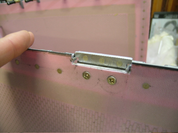
Lastly C I spend five hours redesigning the upper cowl hinge locking mechanism. In my opinion C that thing is a joke. The cowling fiberglass is too thin and when you countersink the #6 screws C it is a recipe for future maintenance and paint problems. The whole mechanism flops around when untightened. Glue in an aluminum back plate to this area so that the screw holes don't get bigger over time and make a sliding mechanism with #426 rivets. That way when you loosen the #6 screws the plate slides straight down and stays aligned with the screw shafts.
I'll send a photo tonight if anyone want to rack their brain for several hours. At least if you do it from the start you won't have to disassemble it which is part of the five hours.
John #409
[quote][b]
| | - The Matronics RV10-List Email Forum - | | | Use the List Feature Navigator to browse the many List utilities available such as the Email Subscriptions page, Archive Search & Download, 7-Day Browse, Chat, FAQ, Photoshare, and much more:
http://www.matronics.com/Navigator?RV10-List |
|
|
|
| Back to top |
|
 |
indigoonlatigo(at)msn.com
Guest
|
| Posted: Mon Nov 09, 2009 10:08 pm Post subject: Cowling alignment and work |
|
|
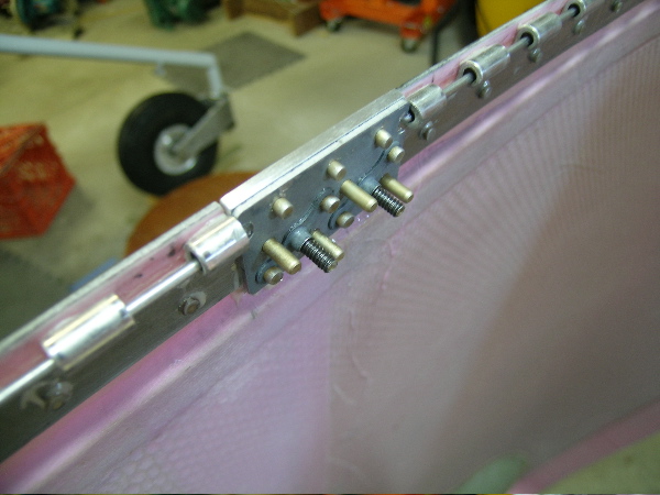
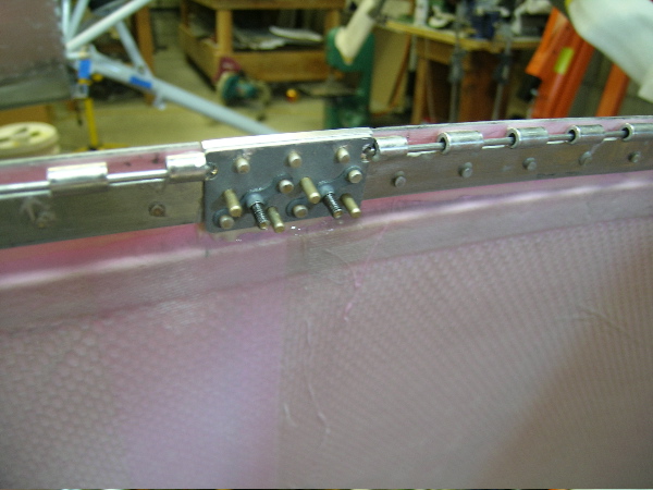
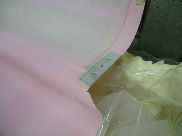
.ExternalClass .ecxhmmessage P {padding:0px;} .ExternalClass body.ecxhmmessage {font-size:10pt;font-family:Verdana;} The idea is that the plate with the nutplates rides along the AN426AD4-6 rivets. The heads of the rivets are sandwitched between the additional plate that acts as a backing plate and is glued to the cowling. The backing plate keeps the screw holes form enlarging and keeps the rivets in place and parallel.
The original design leave the plate that the nutplates are attached to flopping around for and aft when the screws are loosened. It no longer does that.
Use the same plate(the one the nutplates are attached to) that is supplied with the kit C but fabricate a 1/8' aluminum part that engages the pins and levels with the top surface of the cowl. Use nearly 1/16 piece of aluminum for the backing plate C glue this to the cowling after mechanical etch and acid treatment. Use all pieces that came with the kit as drill guides.
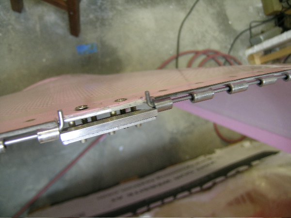
Included a photo of the lower cowl lower attach mechanism C three AN3 screws used per side. Others said that the lower hinge fails after several hours. All hinges and plates are glued with a PTM&W epoxy and the metal was sanded and etched or a sandblaster used for mechanical retention.
John
Date: Mon C 9 Nov 2009 11:45:35 -0800
From: rv10free2fly(at)yahoo.com.au
Subject: Re: Cowling alignment and work
To: indigoonlatigo(at)msn.com
G'day from downunder John C were its a sultry 100F today C and yesterday C and the day before that C and . . . . .
Mate C I'd love to see some photos of your cowl modifications please John C a picture is worth many thousands of words. Your suggestions sound extremly sound and useful in the longer term to save some grief.
Kind regards from down under.
Patrick Pulis
Adelaide C South Australia
From: John Gonzalez <indigoonlatigo(at)msn.com>
To: RV 10 group <rv10-list(at)matronics.com>
Sent: Tue C 10 November C 2009 5:02:21 AM
Subject: Cowling alignment and work
I would like to through in a few thoughts that might help others when working on the cowling.
To begin with C the building instructions seem a little vague in this section so one needs to keep an open mind an improvise when it doesn't make sense.
First C the joggle on the cowl behind the spinner is more like a reference and not a true joggle fit. The instruction make it seem like the two should line up C but they really don't. Only the front part of it does. When lining the upper and lower cowl joggle on this area use a ruler and measure the height of the firewall C then lay the ruler down on the ground underneath the back edge of the the upper and lower cowling while the parts are facing upward. Use this as a reference. Doing this will give you a better idea of how clam shelled the two part should be before you start drilling or cutting anything.
I laid a flat edge across the flat face of the cowling behind the spinner and used a ninety degree angle to scribe a line going back on the inside portion of the air intakes. This trimming and the initial trimming on the outside portion(about 1.5") of the cowling is critical and needs to be done very slowly. One can add back material later but is is extra steps and time.
Make sure you rigidly adhere the items you use to position the top cowling to the spinner. I used 1/8 inch thick paint mixing sticks both for the spacers between the spinner and the pieces which hold it above the spinner. I used Bondo to temporarily adhere these to the top of the cowling and scribed lines from these sticks on the spinner so each time the cowling goes back on it goes on in the same position.
Understand how your original reference lines scribed on the fuse and the cowling parts will slightly change once you trim the excess aft of the hinge areas. The lines on the cowling will be slightly outside of the lines on the fuse as the cowling is laying flatter.
Undoubtedly you may over trim areas. I needed to add 1/32 to 1/8 inch back in certain areas. Because we are adding to a very thin edge and it is very cosmetic in nature C not structural(the hinge is taking the load) I used carbon tows by taping the outside contour of the edge and laying the wetted carbon tows in this edge. I then used a Monojet syringe with epoxy and chopped glass to tie it together. After cure C remove the tape and trim with sanding tools.
Lastly C I spend five hours redesigning the upper cowl hinge locking mechanism. In my opinion C that thing is a joke. The cowling fiberglass is too thin and when you countersink the #6 screws C it is a recipe for future maintenance and paint problems. The whole mechanism flops around when untightened. Glue in an aluminum back plate to this area so that the screw holes don't get bigger over time and make a sliding mechanism with #426 rivets. That way when you loosen the #6 screws the plate slides straight down and stays aligned with the screw shafts.
I'll send a photo tonight if anyone want to rack their brain for several hours. At least if you do it from the start you won't have to disassemble it which is part of the five hours.
John #409
| Quote: | www.aeroelectric.com
/" rel="nofollow">www.buildersbooks.com
nofollow">www.homebuilthelp.com
ow">http://www.matronics.com/contribution
"nofollow">http://www.matronics.com/Navigator?RV10-List
//forums.matronics.com
|
Get more done like never before with Yahoo!7 Mail. Learn more.
| | - The Matronics RV10-List Email Forum - | | | Use the List Feature Navigator to browse the many List utilities available such as the Email Subscriptions page, Archive Search & Download, 7-Day Browse, Chat, FAQ, Photoshare, and much more:
http://www.matronics.com/Navigator?RV10-List |
|
| Description: |
|
| Filesize: |
106.96 KB |
| Viewed: |
1661 Time(s) |
|
| Description: |
|
| Filesize: |
108.59 KB |
| Viewed: |
1661 Time(s) |
|
| Description: |
|
| Filesize: |
102.64 KB |
| Viewed: |
1661 Time(s) |
|
| Description: |
|
| Filesize: |
95.26 KB |
| Viewed: |
1661 Time(s) |
|
| Description: |
|
| Filesize: |
92.99 KB |
| Viewed: |
1661 Time(s) |
|
|
|
| Back to top |
|
|
|
|
You cannot post new topics in this forum
You cannot reply to topics in this forum
You cannot edit your posts in this forum
You cannot delete your posts in this forum
You cannot vote in polls in this forum
You cannot attach files in this forum
You can download files in this forum
|
Powered by phpBB © 2001, 2005 phpBB Group
|

