 |
Matronics Email Lists
Web Forum Interface to the Matronics Email Lists
|
| View previous topic :: View next topic |
| Author |
Message |
Valin
Joined: 13 Apr 2010
Posts: 31
Location: Colorado
|
 Posted: Sun May 23, 2010 8:23 am Post subject: Lancair Flap Drive Relay Wiring Question Posted: Sun May 23, 2010 8:23 am Post subject: Lancair Flap Drive Relay Wiring Question |
 |
|
Hey Aeroelectric Gang,
I’m still working on wiring diagrams for our Lancair Legacy under construction. I have a question on the flap drive wiring I’d appreciate feedback on...
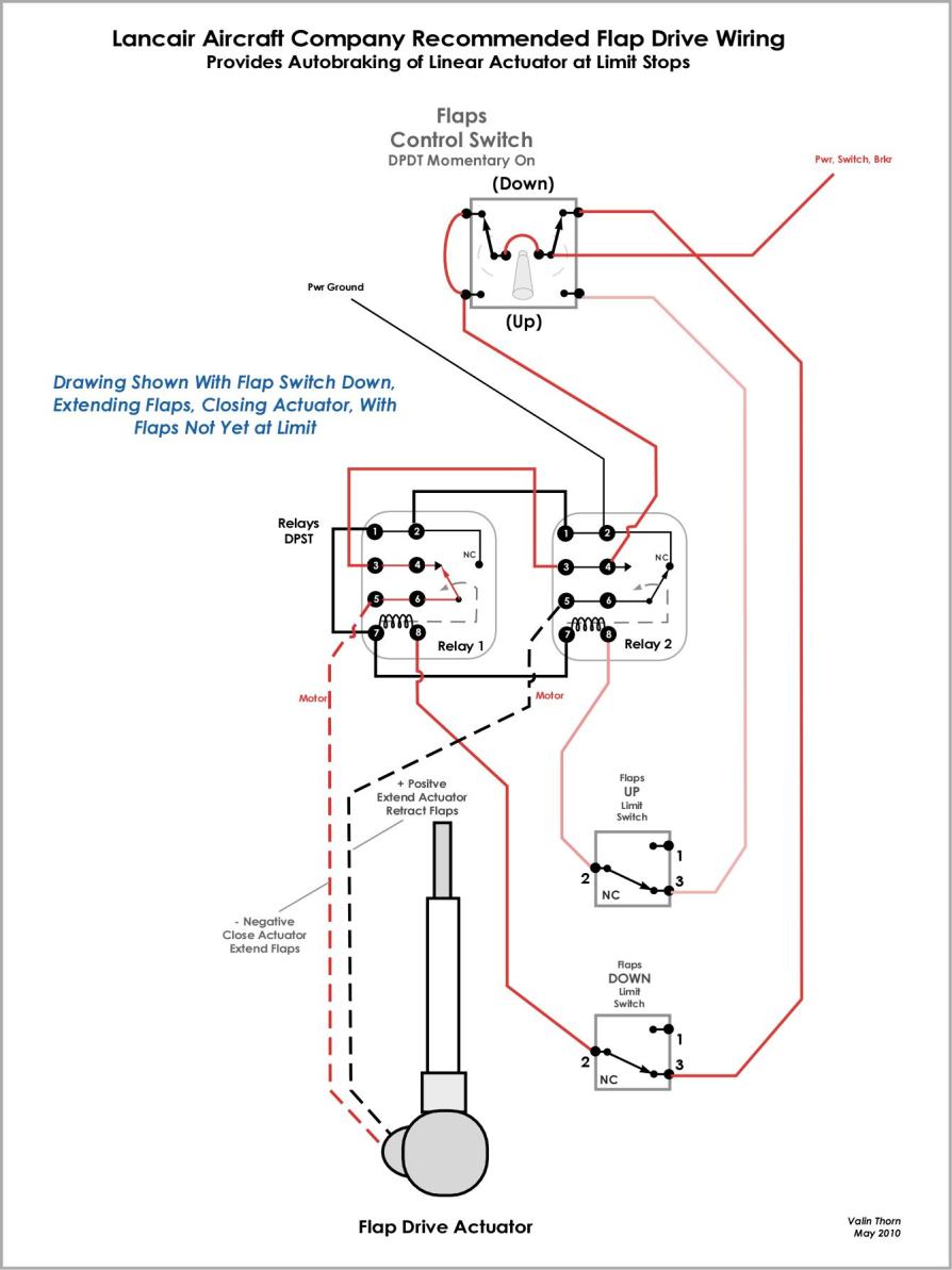
Rather than using a DPDT switch wired up to change polarity for the linear electro-mechanical actuator (EMA) to drive the flaps up and down, Lancair recommends two DPST relays with proper (see below) wiring to change polarity and provide immediate braking of the actuator. Without this circuitry the EMA will coast after releasing the switch which is a serious problem when the flaps are at their limits.
A couple of years ago, when we assembled and installed our flaps, I quickly wired this up and confirmed that without the relays it coasts quite a bit and with this relay circuit the EMA/flaps stop immediately.
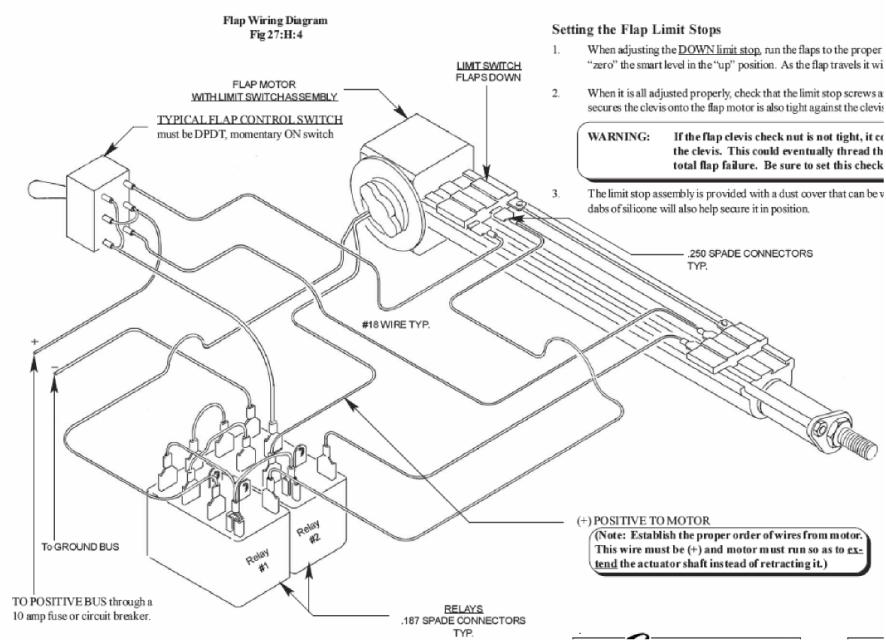
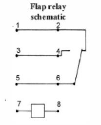
So my question is, how does it accomplish this? I’ve attached my draft wiring diagram where I’ve created what I think is the relay circuit but am not sure. The wiring between everything is accurate. All Lancair provides in their manual is a pictorial of the relay wiring and a schematic of the circuit (see second image below). I’m having to guess that the terminals 7 and 8 in the relay circuit control the switch and that it’s normally closed to pole 2 (the relay schematic from the Lancair manual is the last image below).
Does this braking effect happen because of the collapsing solenoid field provides a brief voltage spike of opposite polarity?
Thanks,
Valin
Lancair Legacy Project
Houston, TX USA
Here’s my rendering of the flap drive wiring as I understand it:
[img]cid:image001.jpg(at)01CAFA69.F50E8500[/img]
[img]cid:image002.jpg(at)01CAFA69.F50E8500[/img]
[img]cid:image005.jpg(at)01CAFA69.F50E8500[/img]
| | - The Matronics AeroElectric-List Email Forum - | | | Use the List Feature Navigator to browse the many List utilities available such as the Email Subscriptions page, Archive Search & Download, 7-Day Browse, Chat, FAQ, Photoshare, and much more:
http://www.matronics.com/Navigator?AeroElectric-List |
|
| Description: |
|
| Filesize: |
84.78 KB |
| Viewed: |
6037 Time(s) |
|
| Description: |
|
| Filesize: |
80.73 KB |
| Viewed: |
6037 Time(s) |
|
| Description: |
|
| Filesize: |
5.06 KB |
| Viewed: |
6037 Time(s) |
|
|
|
| Back to top |
|
 |
retasker(at)optonline.net
Guest
|
| Posted: Sun May 23, 2010 10:13 am Post subject: Lancair Flap Drive Relay Wiring Question |
|
|
When one selects neither up or down with the switch, the motor is
shorted by the relays (each side of the motor goes through its
respective relay's pins 5&6 through the NC connection to pins 1&2 which
are both connected to ground). The fact that they are connected to
ground is incidental. When the power leads of a running DC motor are
shorted together, the motor acts as a generator running into a short.
This almost instantaneously absorbs the rotational energy of the motor,
stopping it very quickly as you saw. If the leads were just disconnected
from power the only way for the rotational energy to dissipate is
through frictional losses in the motor and the flap mechanism - which
allows the whole system to coast to a stop as you found.
Dick Tasker
Valin & Allyson Thorn wrote:
| Quote: |
Hey Aeroelectric Gang,
Im still working on wiring diagrams for our Lancair Legacy under
construction. I have a question on the flap drive wiring Id
appreciate feedback on...
Rather than using a DPDT switch wired up to change polarity for the
linear electro-mechanical actuator (EMA) to drive the flaps up and
down, Lancair recommends two DPST relays with proper (see below)
wiring to change polarity and provide immediate braking of the
actuator. Without this circuitry the EMA will coast after releasing
the switch which is a serious problem when the flaps are at their limits.
A couple of years ago, when we assembled and installed our flaps, I
quickly wired this up and confirmed that without the relays it coasts
quite a bit and with this relay circuit the EMA/flaps stop immediately.
So my question is, how does it accomplish this? Ive attached my draft
wiring diagram where Ive created what I think is the relay circuit
but am not sure. The wiring between everything is accurate. All
Lancair provides in their manual is a pictorial of the relay wiring
and a schematic of the circuit (see second image below). Im having to
guess that the terminals 7 and 8 in the relay circuit control the
switch and that its normally closed to pole 2 (the relay schematic
from the Lancair manual is the last image below).
Does this braking effect happen because of the collapsing solenoid
field provides a brief voltage spike of opposite polarity?
Thanks,
Valin
Lancair Legacy Project
Houston, TX USA
/Heres my rendering of the flap drive wiring as I understand it:/
Lancair Flap Drive Wiring Drawing.jpg
Legacy Flap Wiring Pictorial.jpg
Flap Relay Schematic.jpg
|
--
Please Note:
No trees were destroyed in the sending of this message. We do concede, however,
that a significant number of electrons may have been temporarily inconvenienced.
--
| | - The Matronics AeroElectric-List Email Forum - | | | Use the List Feature Navigator to browse the many List utilities available such as the Email Subscriptions page, Archive Search & Download, 7-Day Browse, Chat, FAQ, Photoshare, and much more:
http://www.matronics.com/Navigator?AeroElectric-List |
|
|
|
| Back to top |
|
|
Valin
Joined: 13 Apr 2010
Posts: 31
Location: Colorado
|
| Posted: Sun May 23, 2010 10:13 am Post subject: Lancair Flap Drive Relay Wiring Question |
|
|
Ironically, I was looking at the Aeroelectric discussions from the last week and saw that Bob in another discussion last Wednesday related to flap drives already explained the motor braking is achieved by grounding (shorting) both sides of the motor rather than just opening the circuit…


     “Note that in the OFF position, both relays

     are relaxed and the wiring places a dead short

     across the motor. This is ESPECIALLY useful in

     PM motors to supply electro-dynamic braking

     to the motor. Coasting is reduced to a small

     fraction of what you get when you simply open

     the motor's power circuit to shut it off.


     Bob . . .”


Thanks Bob.  Sorry I didn’t search the archives more thoroughly before posting my question.  I’d still be interested to know if it looks like I’ve drawn the wiring diagram and relay circuit correctly.


Valin


From: owner-aeroelectric-list-server(at)matronics.com [mailto:owner-aeroelectric-list-server(at)matronics.com] On Behalf Of Valin & Allyson Thorn

 Sent: Sunday, May 23, 2010 11:21 AM

 To: aeroelectric-list(at)matronics.com

 Subject: Lancair Flap Drive Relay Wiring Question


Hey Aeroelectric Gang,


I’m still working on wiring diagrams for our Lancair Legacy under construction.  I have a question on the flap drive wiring I’d appreciate feedback on...


Rather than using a DPDT switch wired up to change polarity for the linear electro-mechanical actuator (EMA) to drive the flaps up and down, Lancair recommends two DPST relays with proper (see below) wiring to change polarity and provide immediate braking of the actuator.  Without this circuitry the EMA will coast after releasing the switch which is a serious problem when the flaps are at their limits.


A couple of years ago, when we assembled and installed our flaps, I quickly wired this up and confirmed that without the relays it coasts quite a bit and with this relay circuit  the EMA/flaps stop immediately.


So my question is, how does it accomplish this?  I’ve attached my draft wiring diagram where I’ve created what I think is the relay circuit but am not sure.  The wiring between everything is accurate.  All Lancair provides in their manual is a pictorial of the relay wiring and a schematic of the circuit (see second image below).  I’m having to guess that the terminals 7 and 8 in the relay circuit control the switch and that it’s normally closed to pole 2 (the relay schematic from the Lancair manual is the last image below).


Does this braking effect happen because of the collapsing solenoid field provides a brief voltage spike of opposite polarity?


Thanks,


Valin

Lancair Legacy Project

Houston, TX USA


Here’s  my rendering of the flap drive wiring as I understand it:


        [quote][b]
| | - The Matronics AeroElectric-List Email Forum - | | | Use the List Feature Navigator to browse the many List utilities available such as the Email Subscriptions page, Archive Search & Download, 7-Day Browse, Chat, FAQ, Photoshare, and much more:
http://www.matronics.com/Navigator?AeroElectric-List |
|
|
|
| Back to top |
|
|
Bob McC
Joined: 09 Jan 2006
Posts: 258
Location: Toronto, ON
|
| Posted: Sun May 23, 2010 12:21 pm Post subject: Lancair Flap Drive Relay Wiring Question |
|
|
Valin;
The wiring as you’ve drawn it appears correct and will function as desired. The second pole of the manual switch which is connected to your power source is not strictly required. Terminals 3 & 4 of the relays could go directly to your circuit protection bypassing the left pole of your switch. A SPDT momentary switch wired as the right side of your DPDT controlling the relays will give the exact same functionality. HOWEVER that second pole gives double redundancy for turning off power to the motor when you release the switch and is probably a good idea.
Also if I understand your explanation of how the flaps work on this aircraft it would appear that the notes on the wires leading to the actuator are incorrect. The drawing shows the red motor lead connected to positive battery power and the black lead grounded. Your explanation says this is extending the flaps and the down limit will stop this motion. The notes associated with the wires are contradictory. (Red lead negative (Therefore Black lead positive) to extend but it also says black lead positive (therefore red lead negative) to retract. Obvious contradiction somewhere). The drawing as shown supports your explanation and it is the notes which appear confused.
Bob McC
From: owner-aeroelectric-list-server(at)matronics.com [mailto:owner-aeroelectric-list-server(at)matronics.com] On Behalf Of Valin & Allyson Thorn
Sent: Sunday, May 23, 2010 2:13 PM
To: aeroelectric-list(at)matronics.com
Subject: RE: Lancair Flap Drive Relay Wiring Question
Ironically, I was looking at the Aeroelectric discussions from the last week and saw that Bob in another discussion last Wednesday related to flap drives already explained the motor braking is achieved by grounding (shorting) both sides of the motor rather than just opening the circuit…
“Note that in the OFF position, both relays
are relaxed and the wiring places a dead short
across the motor. This is ESPECIALLY useful in
PM motors to supply electro-dynamic braking
to the motor. Coasting is reduced to a small
fraction of what you get when you simply open
the motor's power circuit to shut it off.
Bob . . .”
Thanks Bob. Sorry I didn’t search the archives more thoroughly before posting my question. I’d still be interested to know if it looks like I’ve drawn the wiring diagram and relay circuit correctly.
Valin
From: owner-aeroelectric-list-server(at)matronics.com [mailto:owner-aeroelectric-list-server(at)matronics.com] On Behalf Of Valin & Allyson Thorn
Sent: Sunday, May 23, 2010 11:21 AM
To: aeroelectric-list(at)matronics.com
Subject: Lancair Flap Drive Relay Wiring Question
Hey Aeroelectric Gang,
I’m still working on wiring diagrams for our Lancair Legacy under construction. I have a question on the flap drive wiring I’d appreciate feedback on...
Rather than using a DPDT switch wired up to change polarity for the linear electro-mechanical actuator (EMA) to drive the flaps up and down, Lancair recommends two DPST relays with proper (see below) wiring to change polarity and provide immediate braking of the actuator. Without this circuitry the EMA will coast after releasing the switch which is a serious problem when the flaps are at their limits.
A couple of years ago, when we assembled and installed our flaps, I quickly wired this up and confirmed that without the relays it coasts quite a bit and with this relay circuit the EMA/flaps stop immediately.
So my question is, how does it accomplish this? I’ve attached my draft wiring diagram where I’ve created what I think is the relay circuit but am not sure. The wiring between everything is accurate. All Lancair provides in their manual is a pictorial of the relay wiring and a schematic of the circuit (see second image below). I’m having to guess that the terminals 7 and 8 in the relay circuit control the switch and that it’s normally closed to pole 2 (the relay schematic from the Lancair manual is the last image below).
Does this braking effect happen because of the collapsing solenoid field provides a brief voltage spike of opposite polarity?
Thanks,
Valin
Lancair Legacy Project
Houston, TX USA
Here’s my rendering of the flap drive wiring as I understand it:
0123456789
[quote][b]
| | - The Matronics AeroElectric-List Email Forum - | | | Use the List Feature Navigator to browse the many List utilities available such as the Email Subscriptions page, Archive Search & Download, 7-Day Browse, Chat, FAQ, Photoshare, and much more:
http://www.matronics.com/Navigator?AeroElectric-List |
|
_________________
Bob McC
Falco #908
(just starting) |
|
| Back to top |
|
|
jschroeder(at)perigee.net
Guest
|
| Posted: Sun May 23, 2010 12:29 pm Post subject: Lancair Flap Drive Relay Wiring Question |
|
|
Valin-
I would recommend using the circuitry that Lancair has in its manual. It
incorporates what Bob has mentioned (dual relays) in his response to you,
and it works very well - stops instantly when the switch springs back to
the central/neutral position.
I am on the road, but when I get home tomorrow, I can send you the page
from my wirebook with the wiring diagram and pinout of the relays. Let me
know if you want it. I could not download your diagram to enable me to
compare it to mine. Send it off line if you want me to look it over. IMHO,
this is not a circuit in your system that needs any modification.
Regards,
John Schroeder
Lancair ES - 338 hours
| Quote: |
Ironically, I was looking at the Aeroelectric discussions from the last
week
|
| Quote: | and saw that Bob in another discussion last Wednesday related to flap
drives
|
| Quote: | already explained the motor braking is achieved by grounding (shorting)
both
|
| Quote: | sides of the motor rather than just opening the circuit.
"Note that in the OFF position, both relays
are relaxed and the wiring places a dead short
across the motor. This is ESPECIALLY useful in
PM motors to supply electro-dynamic braking
to the motor. Coasting is reduced to a small
fraction of what you get when you simply open
the motor's power circuit to shut it off.
Bob . . ."
|
| | - The Matronics AeroElectric-List Email Forum - | | | Use the List Feature Navigator to browse the many List utilities available such as the Email Subscriptions page, Archive Search & Download, 7-Day Browse, Chat, FAQ, Photoshare, and much more:
http://www.matronics.com/Navigator?AeroElectric-List |
|
|
|
| Back to top |
|
|
longg(at)pjm.com
Guest
|
| Posted: Mon May 24, 2010 6:14 am Post subject: Lancair Flap Drive Relay Wiring Question |
|
|
Do Not Archive


Valin,


I agree with John. Unless you are just curious, don't change a good,

simple thing. I'm sure you've got more important challenges to attend

to.


Glenn Long - Legacy FG.


--
| | - The Matronics AeroElectric-List Email Forum - | | | Use the List Feature Navigator to browse the many List utilities available such as the Email Subscriptions page, Archive Search & Download, 7-Day Browse, Chat, FAQ, Photoshare, and much more:
http://www.matronics.com/Navigator?AeroElectric-List |
|
|
|
| Back to top |
|
|
Valin
Joined: 13 Apr 2010
Posts: 31
Location: Colorado
|
| Posted: Mon May 24, 2010 7:34 am Post subject: Lancair Flap Drive Relay Wiring Question |
|
|
Thanks Glenn and John. I wasn't proposing to change it. I wanted to

understand how the set up made the flap motor stop without coasting

and confirm that I'd reconstructed the relay's internal circuit

acurately.  I understand it well now and think I captured the relay

internal circuit correctly.


Thanks again,


Valin


Sent from my iPhone -- so spleling errors likely...


On May 24, 2010, at 9:12 AM, <longg(at)pjm.com> wrote:


[quote]


 Do Not Archive


 Valin,


 I agree with John. Unless you are just curious, don't change a good,

 simple thing. I'm sure you've got more important challenges to attend

 to.


 Glenn Long - Legacy FG.


 --
| | - The Matronics AeroElectric-List Email Forum - | | | Use the List Feature Navigator to browse the many List utilities available such as the Email Subscriptions page, Archive Search & Download, 7-Day Browse, Chat, FAQ, Photoshare, and much more:
http://www.matronics.com/Navigator?AeroElectric-List |
|
|
|
| Back to top |
|
|
|
|
You cannot post new topics in this forum
You cannot reply to topics in this forum
You cannot edit your posts in this forum
You cannot delete your posts in this forum
You cannot vote in polls in this forum
You cannot attach files in this forum
You can download files in this forum
|
Powered by phpBB © 2001, 2005 phpBB Group
|

