 |
Matronics Email Lists
Web Forum Interface to the Matronics Email Lists
|
| View previous topic :: View next topic |
| Author |
Message |
nuckolls.bob(at)aeroelect
Guest
|
 Posted: Fri Jul 13, 2012 11:32 am Post subject: Contactor redux Posted: Fri Jul 13, 2012 11:32 am Post subject: Contactor redux |
 |
|
At 02:15 PM 7/13/2012, you wrote:


<nuckolls.bob(at)aeroelectric.com>


At 02:03 PM 7/13/2012, you wrote:


Howdy,


I just recieved from B&C a starter contactor S701-1 which, unlike all

the others I've seen, has plastic covers on the mounting tabs. Where

is this guy going to get a coil ground connection? Is the intention

to wire through the switch to ground?


http://www.bandc.biz/pdfs/S701-1_Wiring.pdf


Pax,


  Ed,


  The S701-1 is a continuous duty battery master

  contactor and not intended for service as a

  starter contactor. This is why it is shipped

  configured as a Battery contactor which gets a

  ground through the battery master switch.


  If you wish to use this contactor to control power

  to your starter, you remove the jumper wire installed

  and run your starter push button to the left, small

  terminal. You add a longer jumper from the right,

  small terminal to ground.


  AHA! I see the point of confusion. The B&C wiring

  diagram cited calls for running a fat wire to

  the "starter contactor" which means the HOT side

  of the starter contactor which shares a connection

  to the ship's main bus. This isn't intended to

  imply that this contactor is used for starter

  control.


  The image might better read, "To main bus via hot

                                side of starter contactor"


  If you're looking for a starter contactor . . . I

  suggest you consider the S702-1 or equivalent.


http://tinyurl.com/6p8raot


   Bob . . .


-----

No virus found in this message.

Checked by AVG - www.avg.com


   Bob . . .
| | - The Matronics AeroElectric-List Email Forum - | | | Use the List Feature Navigator to browse the many List utilities available such as the Email Subscriptions page, Archive Search & Download, 7-Day Browse, Chat, FAQ, Photoshare, and much more:
http://www.matronics.com/Navigator?AeroElectric-List |
|
|
|
| Back to top |
|
 |
raymondj(at)frontiernet.n
Guest
|
| Posted: Fri Jul 13, 2012 12:26 pm Post subject: Contactor redux |
|
|
Bob,
I noticed that crimp-on terminals were used on the solid leads on the
diode. It was my understanding that using crimp-ons on solid wire was
not recommended. Am I misinformed....again? 
do not archive
Raymond Julian
Kettle River, MN.
"And you know that I could have me a million more friends,
and all I'd have to lose is my point of view." - John Prine
| Quote: |
Howdy,
I just recieved from B&C a starter contactor S701-1 which, unlike all
the others I've seen, has plastic covers on the mounting tabs. Where is
this guy going to get a coil ground connection? Is the intention to wire
through the switch to ground?
http://www.bandc.biz/pdfs/S701-1_Wiring.pdf
Pax,
Ed,
The S701-1 is a continuous duty battery master
contactor and not intended for service as a
starter contactor. This is why it is shipped
configured as a Battery contactor which gets a
ground through the battery master switch.
-------------------------------snip--------------------------------
|
| | - The Matronics AeroElectric-List Email Forum - | | | Use the List Feature Navigator to browse the many List utilities available such as the Email Subscriptions page, Archive Search & Download, 7-Day Browse, Chat, FAQ, Photoshare, and much more:
http://www.matronics.com/Navigator?AeroElectric-List |
|
|
|
| Back to top |
|
|
nuckolls.bob(at)aeroelect
Guest
|
| Posted: Fri Jul 13, 2012 3:47 pm Post subject: Contactor redux |
|
|
At 03:22 PM 7/13/2012, you wrote:
| Quote: | --> AeroElectric-List message posted by: rayj <raymondj(at)frontiernet.net>
Bob,
I noticed that crimp-on terminals were used on the solid leads on the diode. It was my understanding that using crimp-ons on solid wire was not recommended. Am I misinformed....again?
|
Is that something I wrote? If it was, I cannot recall
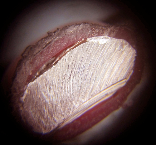
a context where that would be true. Here's a photomicrograph
I just shot for 22AWG solid wire (diode lead) crimped into a
red PIDG using an el-cheapo crimp tool.
[img]cid:7.1.0.9.0.20120713183738.01e17628(at)aeroelectric.com.0[/img]
I couldn't find my polishing disk so the smoothed end is
rather rough. Normally you'd be able to see the ring of
tin plating on the wire at the interface between wire
and terminal barrel. Nonetheless, this photo confirms that
the two metals to be joined have been upset with sufficient
force to make them essentially one with no voids.
Bob . . .
| | - The Matronics AeroElectric-List Email Forum - | | | Use the List Feature Navigator to browse the many List utilities available such as the Email Subscriptions page, Archive Search & Download, 7-Day Browse, Chat, FAQ, Photoshare, and much more:
http://www.matronics.com/Navigator?AeroElectric-List |
|
| Description: |
|
| Filesize: |
159.56 KB |
| Viewed: |
2645 Time(s) |
|
|
|
| Back to top |
|
|
raymondj(at)frontiernet.n
Guest
|
| Posted: Fri Jul 13, 2012 4:21 pm Post subject: Contactor redux |
|
|
I thought I saw it one of the electronics catalogs. I'll do a little
looking around and see if I can find where I saw it. Thanks again for
the info.
Raymond Julian
Kettle River, MN.
"And you know that I could have me a million more friends,
and all I'd have to lose is my point of view." - John Prine
On 07/13/2012 06:42 PM, Robert L. Nuckolls, III wrote:
| Quote: | At 03:22 PM 7/13/2012, you wrote:
>
>
> Bob,
>
> I noticed that crimp-on terminals were used on the solid leads on the
> diode. It was my understanding that using crimp-ons on solid wire was
> not recommended. Am I misinformed....again?
Is that something I wrote? If it was, I cannot recall
a context where that would be true. Here's a photomicrograph
I just shot for 22AWG solid wire (diode lead) crimped into a
red PIDG using an el-cheapo crimp tool.
Emacs!
I couldn't find my polishing disk so the smoothed end is
rather rough. Normally you'd be able to see the ring of
tin plating on the wire at the interface between wire
and terminal barrel. Nonetheless, this photo confirms that
the two metals to be joined have been upset with sufficient
force to make them essentially one with no voids.
Bob . . .
|
| | - The Matronics AeroElectric-List Email Forum - | | | Use the List Feature Navigator to browse the many List utilities available such as the Email Subscriptions page, Archive Search & Download, 7-Day Browse, Chat, FAQ, Photoshare, and much more:
http://www.matronics.com/Navigator?AeroElectric-List |
|
|
|
| Back to top |
|
|
|
|
You cannot post new topics in this forum
You cannot reply to topics in this forum
You cannot edit your posts in this forum
You cannot delete your posts in this forum
You cannot vote in polls in this forum
You cannot attach files in this forum
You can download files in this forum
|
Powered by phpBB © 2001, 2005 phpBB Group
|

