 |
Matronics Email Lists
Web Forum Interface to the Matronics Email Lists
|
| View previous topic :: View next topic |
| Author |
Message |
n744bh(at)bellsouth.net
Guest
|
 Posted: Fri Jul 20, 2012 12:04 pm Post subject: troubleshooting help needed Posted: Fri Jul 20, 2012 12:04 pm Post subject: troubleshooting help needed |
 |
|
Here's the problem that has me scratching my  head.  I have a Glasair Super 2 that's been flying with no problems for  over 100 hours.  The electric system is Z 11, 14 volt.  The engine is  a Lycoming IO360 and the alternator is the one that came with the engine and of  Chrysler origin for aircraft use.  I'm told that they are fairly  bulletproof.  It was completely overhauled before I started flying.   The voltage regulator is a B & C LR3C.


 So here's the problem which has popped up in the  last 15 hours or so.  When I'm flying at cruise power, or even idling, the  voltage wanders up and down from 14.4v to slightly less than 13v.  It does  go down enough that my Garmin Aera 796 will drop off of ships power and go to  it's internal battery.  This would indicate to me that this is not a  problem with the voltmeter. This does not seem to have any measurable  cycle.  The amps stay constant at about 16 amps.  When I've had the  plane flying I've tried turning off equipment one at a time to see if that might  have any effect...it didn't.


 I've checked my connections for any corrosion and  everything looks good and tight, including the alternator belt.   The next  thing I'm going to do is run the B&C troubleshooting checklist but I thought  I would put this out for the list to see if anyone has any ideas that I haven't  thought of that I might check.  I personally suspect the LR3C but the folks  at B&C have their doubts.  So what y'all think?


 Bill

 Glasair SIIS-FT


   [quote][b]
| | - The Matronics AeroElectric-List Email Forum - | | | Use the List Feature Navigator to browse the many List utilities available such as the Email Subscriptions page, Archive Search & Download, 7-Day Browse, Chat, FAQ, Photoshare, and much more:
http://www.matronics.com/Navigator?AeroElectric-List |
|
|
|
| Back to top |
|
 |
bbradburry(at)bellsouth.n
Guest
|
| Posted: Fri Jul 20, 2012 12:10 pm Post subject: troubleshooting help needed |
|
|
Bill,
I am having a similar problem with my Lancair. The voltage seems to float up and down about a half volt and I have had problems with the transponder shutting down and the moving map resets. I hope my problem is your problem and someone has a solution.
Bill B
From: owner-aeroelectric-list-server(at)matronics.com [mailto:owner-aeroelectric-list-server(at)matronics.com] On Behalf Of Bill Hibbing
Sent: Friday, July 20, 2012 4:02 PM
To: aeroelectric-list(at)matronics.com
Subject: AeroElectric-List: troubleshooting help needed
Here's the problem that has me scratching my head. I have a Glasair Super 2 that's been flying with no problems for over 100 hours. The electric system is Z 11, 14 volt. The engine is a Lycoming IO360 and the alternator is the one that came with the engine and of Chrysler origin for aircraft use. I'm told that they are fairly bulletproof. It was completely overhauled before I started flying. The voltage regulator is a B & C LR3C.
So here's the problem which has popped up in the last 15 hours or so. When I'm flying at cruise power, or even idling, the voltage wanders up and down from 14.4v to slightly less than 13v. It does go down enough that my Garmin Aera 796 will drop off of ships power and go to it's internal battery. This would indicate to me that this is not a problem with the voltmeter. This does not seem to have any measurable cycle. The amps stay constant at about 16 amps. When I've had the plane flying I've tried turning off equipment one at a time to see if that might have any effect...it didn't.
I've checked my connections for any corrosion and everything looks good and tight, including the alternator belt. The next thing I'm going to do is run the B&C troubleshooting checklist but I thought I would put this out for the list to see if anyone has any ideas that I haven't thought of that I might check. I personally suspect the LR3C but the folks at B&C have their doubts. So what y'all think?
Bill
Glasair SIIS-FT
| Quote: | | http://www.matronics.com/Navigator?AeroElectric-List |
0123456789
[quote][b]
| | - The Matronics AeroElectric-List Email Forum - | | | Use the List Feature Navigator to browse the many List utilities available such as the Email Subscriptions page, Archive Search & Download, 7-Day Browse, Chat, FAQ, Photoshare, and much more:
http://www.matronics.com/Navigator?AeroElectric-List |
|
|
|
| Back to top |
|
|
nuckolls.bob(at)aeroelect
Guest
|
| Posted: Fri Jul 20, 2012 5:00 pm Post subject: troubleshooting help needed |
|
|
At 03:02 PM 7/20/2012, you wrote:
Here's the problem that has me scratching my head. I have a Glasair Super 2 that's been flying with no problems for over 100 hours. The electric system is Z 11, 14 volt. The engine is a Lycoming IO360 and the alternator is the one that came with the engine and of Chrysler origin for aircraft use. I'm told that they are fairly bulletproof. It was completely overhauled before I started flying. The voltage regulator is a B & C LR3C.
So here's the problem which has popped up in the last 15 hours or so. When I'm flying at cruise power, or even idling, the voltage wanders up and down from 14.4v to slightly less than 13v. It does go down enough that my Garmin Aera 796 will drop off of ships power and go to it's internal battery. This would indicate to me that this is not a problem with the voltmeter. This does not seem to have any measurable cycle. The amps stay constant at about 16 amps. When I've had the plane flying I've tried turning off equipment one at a time to see if that might have any effect...it didn't.
I've checked my connections for any corrosion and everything looks good and tight, including the alternator belt. The next thing I'm going to do is run the B&C troubleshooting checklist but I thought I would put this out for the list to see if anyone has any ideas that I haven't thought of that I might check. I personally suspect the LR3C but the folks at B&C have their doubts. So what y'all think?
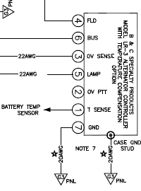
You need to bring three wires into the cockpit from
the regulator. One that is attached to the field output
terminal (4), another to ov-sense input (3) and a third
to ground (7).
[img]cid:.0[/img]
You need to watch and record the voltage reading between
ground (7) and field (4) when the alternator is operating
normally at minimum system loads and maximum system loads.
Then move your test voltmeter to read voltage between ground
(7) and ov-sense (3). Repeat the min/max loads experiment
and compare the readings on the test voltmeter and any
panel displays for bus voltage.
Then when the alternator is mis-behaving under any normal
operating load, does the field voltage go UP as the
bus voltage indications on the panel go down . . . or
vice-versa? Also, during misbehavior notice if there
is any deviation from ov-sense readings you acquired
earlier and panel displayed voltage readings.
If the alternator is working properly, Field and Bus voltage
should go up and down together in response to output
from the regulator.
If they are out of sync . . . then the alternator is bad
(probably failing brushes). If they go up and down together,
then move your test meter.
If they do go up and down together, then turn your attention
to the difference between panel voltage display and test
meter. Are the differences markedly dissimilar from when the
alternator was working?
This exercise in data gathering allows one to deduce
whether the problem lies in the alternator, regulator
or ship's wiring.
Bob . . .
| | - The Matronics AeroElectric-List Email Forum - | | | Use the List Feature Navigator to browse the many List utilities available such as the Email Subscriptions page, Archive Search & Download, 7-Day Browse, Chat, FAQ, Photoshare, and much more:
http://www.matronics.com/Navigator?AeroElectric-List |
|
| Description: |
|
| Filesize: |
30.69 KB |
| Viewed: |
3640 Time(s) |

|
|
|
| Back to top |
|
|
JLuckey(at)pacbell.net
Guest
|
| Posted: Fri Jul 20, 2012 5:34 pm Post subject: troubleshooting help needed |
|
|
See my question inserted about 3/4 way down the page…


-Jeff Luckey


From: owner-aeroelectric-list-server(at)matronics.com [mailto:owner-aeroelectric-list-server(at)matronics.com] On Behalf Of Robert L. Nuckolls, III

 Sent: Friday, July 20, 2012 17:59

 To: aeroelectric-list(at)matronics.com

 Subject: Re: AeroElectric-List: troubleshooting help needed


At 03:02 PM 7/20/2012, you wrote:

 Here's the problem that has me scratching my head.  I have a Glasair Super 2 that's been flying with no problems for over 100 hours.  The electric system is Z 11, 14 volt.  The engine is a Lycoming IO360 and the alternator is the one that came with the engine and of Chrysler origin for aircraft use.  I'm told that they are fairly bulletproof.  It was completely overhauled before I started flying.  The voltage regulator is a B & C LR3C.


 So here's the problem which has popped up in the last 15 hours or so.  When I'm flying at cruise power, or even idling, the voltage wanders up and down from 14.4v to slightly less than 13v.  It does go down enough that my Garmin Aera 796 will drop off of ships power and go to it's internal battery.  This would indicate to me that this is not a problem with the voltmeter. This does not seem to have any measurable cycle.  The amps stay constant at about 16 amps.  When I've had the plane flying I've tried turning off equipment one at a time to see if that might have any effect...it didn't.


 I've checked my connections for any corrosion and everything looks good and tight, including the alternator belt.   The next thing I'm going to do is run the B&C troubleshooting checklist but I thought I would put this out for the list to see if anyone has any ideas that I haven't thought of that I might check.  I personally suspect the LR3C but the folks at B&C have their doubts.  So what y'all think?


     You need to bring three wires into the cockpit from

     the regulator. One that is attached to the field output

     terminal (4), another to ov-sense input (3) and a third

     to ground (7).


 [img]cid:image001.jpg(at)01CD66A5.BF83DF20[/img]


     You need to watch and record the voltage reading between

     ground (7) and field (4) when the alternator is operating

     normally at minimum system loads and maximum system loads.


     Then move your test voltmeter to read voltage between ground

     (7) and ov-sense (3). Repeat the min/max loads experiment

     and compare the readings on the test voltmeter and any

     panel displays for bus voltage.


     Then when the alternator is mis-behaving under any normal

     operating load, does the field voltage go UP as the

     bus voltage indications on the panel go down . . . or

     vice-versa? Also, during misbehavior notice if there

     is any deviation from ov-sense readings you acquired

     earlier and panel displayed voltage readings.


     If the alternator is working properly, Field and Bus voltage

     should go up and down together in response to output

     from the regulator.


[Luckey]

Bob, is that correct - shouldn’t Field & Bus voltage oppose each other?

i.e. as Bus voltage goes up, Field current should go down?


     If they are out of sync . . . then the alternator is bad

     (probably failing brushes). If they go up and down together,

     then move your test meter.


     If they do go up and down together, then turn your attention

     to the difference between panel voltage display and test

     meter. Are the differences markedly dissimilar from when the

     alternator was working?


     This exercise in data gathering allows one to deduce

     whether the problem lies in the alternator, regulator

     or ship's wiring.


  Bob . . .
| | - The Matronics AeroElectric-List Email Forum - | | | Use the List Feature Navigator to browse the many List utilities available such as the Email Subscriptions page, Archive Search & Download, 7-Day Browse, Chat, FAQ, Photoshare, and much more:
http://www.matronics.com/Navigator?AeroElectric-List |
|
| Description: |
|
| Filesize: |
30.69 KB |
| Viewed: |
3640 Time(s) |
|
|
|
| Back to top |
|
|
nuckolls.bob(at)aeroelect
Guest
|
| Posted: Sat Jul 21, 2012 5:46 am Post subject: troubleshooting help needed |
|
|
At 03:10 PM 7/20/2012, you wrote:
| Quote: | Bill,
I am having a similar problem with my Lancair. The voltage seems to float up and down about a half volt and I have had problems with the transponder shutting down and the moving map resets. I hope my problem is your problem and someone has a solution.
Bill B
|
If a .5 volt excursion is causing your electro-whizzies
to misbehave, there's something else going on.
While it's viscerally satisfying to see a bus voltage reading
stay locked down to within a tenth of a volt of the
set point, having it vary by 1/2 volt under repeatable
conditions should not be an operational issue.
Your bus voltage should fly somewhere north of 14.0
volts . . . 14.2 was the 'sweet spot' when I worked
at Cessna . . . 14.6 to as much as 15.0 volts seems
to show up in contemporary automotive products.
But 14.0 is the operating floor for making sure
that a battery gets topped off a short time
after takeoff.
If your transponder is qualified for use in a
type certficated airplane, it should operate without
complaint down to end-of-battery-life voltage levels
on the order of 11.0 volts. The moving map should
be similarly qualified. For these devices to complain
in concert suggests an intermittent condition that
drops to levels much below your panel displays for
bus voltage . . . a voltage level below battery
supply voltage even. Loose connection?
Bob . . . [quote][b]
| | - The Matronics AeroElectric-List Email Forum - | | | Use the List Feature Navigator to browse the many List utilities available such as the Email Subscriptions page, Archive Search & Download, 7-Day Browse, Chat, FAQ, Photoshare, and much more:
http://www.matronics.com/Navigator?AeroElectric-List |
|
|
|
| Back to top |
|
|
nuckolls.bob(at)aeroelect
Guest
|
| Posted: Sat Jul 21, 2012 6:27 am Post subject: troubleshooting help needed |
|
|
At 08:33 PM 7/20/2012, you wrote:


[Luckey]

Bob, is that correct - shouldn't Field & Bus voltage oppose each other?

i.e. as Bus voltage goes up, Field current should go down?


    It depends on what is being held constant and what

    is being adjusted.


    If SYSTEM LOAD is the variable, then yes . . . the

    REGULATOR senses an INCREASE in bus voltage and

    reacts by REDUCING field voltage.


    In this instance, we're observing changes in

    system performance while the load is constant.

    If the field voltage rises in concert with the

    bus voltage, then the regulator is commanding

    that rise due to internal failure or mis-information

    in the voltage sense path and the alternator

    is performing normally.


    If the bus voltage falls while the field voltage

    rises, then the regulator is flogging a crippled

    alternator without success.


   Bob . . .
| | - The Matronics AeroElectric-List Email Forum - | | | Use the List Feature Navigator to browse the many List utilities available such as the Email Subscriptions page, Archive Search & Download, 7-Day Browse, Chat, FAQ, Photoshare, and much more:
http://www.matronics.com/Navigator?AeroElectric-List |
|
|
|
| Back to top |
|
|
n744bh(at)bellsouth.net
Guest
|
| Posted: Thu Jul 26, 2012 7:15 pm Post subject: troubleshooting help needed |
|
|
OK, here's an update on what I've found without the engine running and using

the B&C LR3C troubleshooting checklist.


Step one gave me zero ohms resistance from the battery (-) to LR3C pin 7 and

the same from the battery (-) to the engine case.


Step two gave me a battery bus voltage of 12.64v and a pin 3 voltage of

12.62v.


Step three gave me a pin 6 voltage of 12.20, well within the 0.5v tolerance.

So far so good.


Step four gave me a pin 4 voltage of 11.20v, well within the desired range.


Step five.  Here's where the fun begins.  I measured the voltage at the

field terminal and it was zero.  Thinking that there may be a continuity

problem I pulled the alternator field lead off the alternator and checked

again...no voltage.  I turned off the power and checked the continuity and

found it was good.  I also checked the alternator field resistance and it

came in at 30.6 ohms.


So now I think I may have some sort of a problem here so I hooked everything

back up and went back to step 4 and checked pin 4 again.  This time it was

1.73 volts at both pin 4 and at the alternator field terminal.


The folks at B&C are at Oshkosh right now so getting hold of them might be

difficult but maybe Bob can weigh in again on this one.


Bill

Glasair SIIS-FT

---
| | - The Matronics AeroElectric-List Email Forum - | | | Use the List Feature Navigator to browse the many List utilities available such as the Email Subscriptions page, Archive Search & Download, 7-Day Browse, Chat, FAQ, Photoshare, and much more:
http://www.matronics.com/Navigator?AeroElectric-List |
|
|
|
| Back to top |
|
|
nuckolls.bob(at)aeroelect
Guest
|
| Posted: Fri Jul 27, 2012 8:14 am Post subject: troubleshooting help needed |
|
|
Your original squawk:


          When I'm flying at cruise power, or even idling, the voltage wanders up and down

         from 14.4v to slightly less than 13v.  It does go down enough that my Garmin

         Aera 796 will drop off of ships power and go to it's internal battery.  This would

         indicate to me that this is not a problem with the voltmeter. This does not seem

         to have any measurable cycle.  The amps stay constant at about 16 amps.

         When I've had the plane flying I've tried turning off equipment one at a time to

         see if that might have any effect...it didn't.


         So now I think I may have some sort of a problem

         here so I hooked everything back up and went back

         to step 4 and checked pin 4 again.  This time it

         was 1.73 volts at both pin 4 and at the alternator

         field terminal.


 You didn't tell us where your ammeter was connected . . .

 in other words, what current does it measure?


 The fact that your bus voltage falls so low (13.0 or below)

 suggests the alternator is going off line completely and that

 the bus voltage is falling to battery delivery voltage.


 Your narrative also suggests that your ammeter is looking at

 ship's loads and not alternator output which would explain

 the relatively constant ammeter reading.


         So now I think I may have some sort of a problem

         here so I hooked everything back up and went back

         to step 4 and checked pin 4 again.  This time it

         was 1.73 volts at both pin 4 and at the alternator

         field terminal.


 This is consistent with an intermittent disconnect of

 alternator field supply which. If the voltage at pin 4

 ever drops so low while pin 6 and 3 are at battery

 voltage points to failure within the regulator. Suggest

 you arrange to return it to B&C for inspection/repair.


   Bob . . .    [quote][b]
| | - The Matronics AeroElectric-List Email Forum - | | | Use the List Feature Navigator to browse the many List utilities available such as the Email Subscriptions page, Archive Search & Download, 7-Day Browse, Chat, FAQ, Photoshare, and much more:
http://www.matronics.com/Navigator?AeroElectric-List |
|
|
|
| Back to top |
|
|
n744bh(at)bellsouth.net
Guest
|
| Posted: Fri Jul 27, 2012 8:47 am Post subject: troubleshooting help needed |
|
|
Thanks Bob,
That's about what I was thinking also. I was hoping that I would find the alternator was the problem as it's a heck of a lot easier to change. Another question for you...I currently have the LR3C mounted on the cabin side of the firewall. Do you see any problem with relocating it to the engine side of the firewall? As long as I have to take it out, a real PITA, I thought I might change the location to a location that is easier to work on it in the case of another failure. Thanks,
Bill
[quote]
So now I think I may have some sort of a problem
here so I hooked everything back up and went back
to step 4 and checked pin 4 again. This time it
was 1.73 volts at both pin 4 and at the alternator
field terminal.
This is consistent with an intermittent disconnect of
alternator field supply which. If the voltage at pin 4
ever drops so low while pin 6 and 3 are at battery
voltage points to failure within the regulator. Suggest
you arrange to return it to B&C for inspection/repair.
Bob . . .
| Quote: |
href="http://www.matronics.com/Navigator?AeroElectric-List">http://www.matronics.com/Navigator?AeroElectric-List
href="http://forums.matronics.com">http://forums.matronics.com
href="http://www.matronics.com/contribution">http://www.matronics.com/c
|
No virus found in this message.
Checked by AVG - www.avg.com
Version: 2012.0.2197 / Virus Database: 2437/5158 - Release Date: 07/27/12[b]
| | - The Matronics AeroElectric-List Email Forum - | | | Use the List Feature Navigator to browse the many List utilities available such as the Email Subscriptions page, Archive Search & Download, 7-Day Browse, Chat, FAQ, Photoshare, and much more:
http://www.matronics.com/Navigator?AeroElectric-List |
|
|
|
| Back to top |
|
|
ceengland7(at)gmail.com
Guest
|
| Posted: Fri Jul 27, 2012 11:18 am Post subject: troubleshooting help needed |
|
|
On 07/27/2012 11:10 AM, Robert L. Nuckolls, III wrote: | Quote: | Your original squawk:
When I'm flying at cruise power, or even idling, the voltage wanders up and down
from 14.4v to slightly less than 13v. It does go down enough that my Garmin
Aera 796 will drop off of ships power and go to it's internal battery. This would
indicate to me that this is not a problem with the voltmeter. This does not seem
to have any measurable cycle. The amps stay constant at about 16 amps.
When I've had the plane flying I've tried turning off equipment one at a time to
see if that might have any effect...it didn't.
So now I think I may have some sort of a problem
here so I hooked everything back up and went back
to step 4 and checked pin 4 again. This time it
was 1.73 volts at both pin 4 and at the alternator
field terminal.
You didn't tell us where your ammeter was connected . . .
in other words, what current does it measure?
The fact that your bus voltage falls so low (13.0 or below)
suggests the alternator is going off line completely and that
the bus voltage is falling to battery delivery voltage.
Your narrative also suggests that your ammeter is looking at
ship's loads and not alternator output which would explain
the relatively constant ammeter reading.
So now I think I may have some sort of a problem
here so I hooked everything back up and went back
to step 4 and checked pin 4 again. This time it
was 1.73 volts at both pin 4 and at the alternator
field terminal.
This is consistent with an intermittent disconnect of
alternator field supply which. If the voltage at pin 4
ever drops so low while pin 6 and 3 are at battery
voltage points to failure within the regulator. Suggest
you arrange to return it to B&C for inspection/repair.
Bob . . .
|
Since the field voltage at the alt wasn't there, & came back after the disconnect/reconnect, it might be worthwhile to disconnect it again & do a resistance check while wiggling the wire & terminations, prior to returning the regulator.
Charlie
[quote][b]
| | - The Matronics AeroElectric-List Email Forum - | | | Use the List Feature Navigator to browse the many List utilities available such as the Email Subscriptions page, Archive Search & Download, 7-Day Browse, Chat, FAQ, Photoshare, and much more:
http://www.matronics.com/Navigator?AeroElectric-List |
|
|
|
| Back to top |
|
|
nuckolls.bob(at)aeroelect
Guest
|
| Posted: Fri Jul 27, 2012 3:48 pm Post subject: troubleshooting help needed |
|
|
At 11:45 AM 7/27/2012, you wrote:
| Quote: | Thanks Bob,
That's about what I was thinking also. I was hoping that I would find the alternator was the problem as it's a heck of a lot easier to change. Another question for you...I currently have the LR3C mounted on the cabin side of the firewall. Do you see any problem with relocating it to the engine side of the firewall? As long as I have to take it out, a real PITA, I thought I might change the location to a location that is easier to work on it in the case of another failure. Thanks, |
Many of them are located on the engine side
of the fire wall and seem to do just fine.
We designed that critter 25 years ago and I
never did an on-purpose thermal study. I should
probably get one from Bill and put it in the
chamber to see what the real ambient limits
are.
Actually, temperatures on the fire wall while
in flight are quite benign. That's another real
data gathering exercise that would be useful
to conduct.
All it takes is time and $ . . . but you're
okay if you move it.
Bob . . . [quote][b]
| | - The Matronics AeroElectric-List Email Forum - | | | Use the List Feature Navigator to browse the many List utilities available such as the Email Subscriptions page, Archive Search & Download, 7-Day Browse, Chat, FAQ, Photoshare, and much more:
http://www.matronics.com/Navigator?AeroElectric-List |
|
|
|
| Back to top |
|
|
|
|
You cannot post new topics in this forum
You cannot reply to topics in this forum
You cannot edit your posts in this forum
You cannot delete your posts in this forum
You cannot vote in polls in this forum
You cannot attach files in this forum
You can download files in this forum
|
Powered by phpBB © 2001, 2005 phpBB Group
|

