 |
Matronics Email Lists
Web Forum Interface to the Matronics Email Lists
|
| View previous topic :: View next topic |
| Author |
Message |
james(at)etravel.org
Guest
|
 Posted: Fri Sep 27, 2013 8:21 am Post subject: Multiplexing 7-segment LED displays Posted: Fri Sep 27, 2013 8:21 am Post subject: Multiplexing 7-segment LED displays |
 |
|
I'm wondering if anyone can answer this question:Â
I'd like to build a new fuel gauge based around 7-segment LED displays, driven by a PIC / Arduino, etc. Â Instead of running dozens of IO lines, I'd like to multiplex the displays so that the total number of lines is 7 + (no. of digits). Â
The idea would be to switch on a common line for each digit in turn, and set the state for the seven segment lines for the digit that's currently lit. Â
I hope that makes sense.
Anyway, I'm sure the software will be straightforward enough (he says!) but it's the circuitry with which I need some help.  Can anyone recommend a few components to drive the LED displays from the PIC, along with a circuit diagram?  I have a bunch of resistors and general purpose transistors in my electronics kit.  I'd probably test this on a PIC18F4680, because I have a neat little prototype board with this particular chip, along with HDSP-315E 7-segment digits, which is a common anode type.Â
Happy to share my findings with anyone who's interested!
Many thanks,
James
[quote][b]
| | - The Matronics AeroElectric-List Email Forum - | | | Use the List Feature Navigator to browse the many List utilities available such as the Email Subscriptions page, Archive Search & Download, 7-Day Browse, Chat, FAQ, Photoshare, and much more:
http://www.matronics.com/Navigator?AeroElectric-List |
|
|
|
| Back to top |
|
 |
nuckolls.bob(at)aeroelect
Guest
|
| Posted: Fri Sep 27, 2013 10:38 am Post subject: Multiplexing 7-segment LED displays |
|
|
At 11:20 AM 9/27/2013, you wrote:
I'm wondering if anyone can answer this question:Â
I'd like to build a new fuel gauge based around 7-segment LED displays, driven by a PIC / Arduino, etc. Â Instead of running dozens of IO lines, I'd like to multiplex the displays so that the total number of lines is 7 + (no. of digits). Â
The idea would be to switch on a common line for each digit in turn, and set the state for the seven segment lines for the digit that's currently lit. Â
I hope that makes sense.
That's the way it's usually done. I don't think anybody runs
multiple 7-segment displays statically.
Anyway, I'm sure the software will be straightforward enough (he says!) but it's the circuitry with which I need some help.  Can anyone recommend a few components to drive the LED displays from the PIC, along with a circuit diagram?  I have a bunch of resistors and general purpose transistors in my electronics kit.  I'd probably test this on a PIC18F4680, because I have a neat little prototype board with this particular chip, along with HDSP-315E 7-segment digits, which is a common anode type.Â
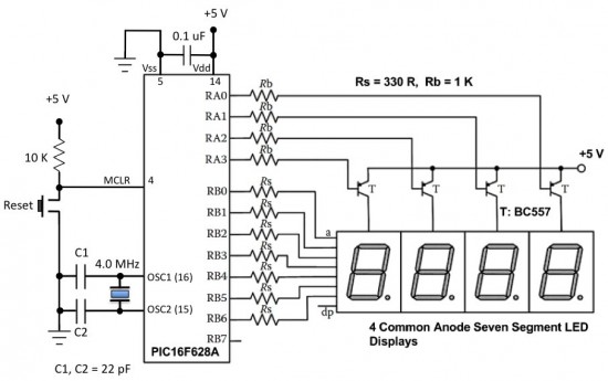
The pull down capability of a PIC port is on the order
of 30mA Your common anode displays would be switched
on, in turn, by pulling down on the base of a PNP transistor.
The collector of said transistor would drive the anode
of one display . . . possible fitted with a resistor to
limit current.
This image shows the general arrangement . . . in this
case segment current limits are in the cathodes . . . it
can be on the anode side if you light only one segment at
a time, if it's one full digit at a time, you'll want to
use cathode positioned current limits.
See http://tinyurl.com/ks5aos5
There are a host of approaches for both schematic and source
codes published on the net.
See:
http://tinyurl.com/m5wffq5
How do you plan to sense liquid level?
Bob . . . [quote][b]
| | - The Matronics AeroElectric-List Email Forum - | | | Use the List Feature Navigator to browse the many List utilities available such as the Email Subscriptions page, Archive Search & Download, 7-Day Browse, Chat, FAQ, Photoshare, and much more:
http://www.matronics.com/Navigator?AeroElectric-List |
|
|
|
| Back to top |
|
|
james(at)etravel.org
Guest
|
| Posted: Fri Sep 27, 2013 11:21 am Post subject: Multiplexing 7-segment LED displays |
|
|
| Quote: | This image shows the general arrangement
|
Thanks Bob, that's a great help, thanks. Â I'll breadboard it and see how I get on. Â Presumably with your circuit, if I assemble the transistor / LED arrays, I can test them by putting 5V into the resistors, just like the PIC outputs would. Â
| Quote: | How do you plan to sense liquid level?
|
I have three of the excellent Princeton capacitive sensors. Â After calibration, they will linearise a fuel tank's output and give a 0 - 5V output from empty to full.
I've produced a version using a colour LCD, and the software works well, but it's not very clear in direct sunlight. Â The great thing about the LCD though is the ability to show fuel quantities in red or green according to the level in a particular tank, e.g. <10% = red.
The ideal thing would be to find a nice bright OLED display.  That would be the best of both worlds.  I have ideas about an all-in-one OLED instrument that would show fuel, temperatures, pressures, etc. -- a complete engine management system in one drop-in 2-1/4" or 3-1/8" package.  I have thermocouple chips ready to do some prototyping... but I'm short on time and have to stick to paying projects at the moment. Â
James
On 27 September 2013 19:37, Robert L. Nuckolls, III <nuckolls.bob(at)aeroelectric.com (nuckolls.bob(at)aeroelectric.com)> wrote:
[quote] At 11:20 AM 9/27/2013, you wrote:
I'm wondering if anyone can answer this question:Ã
I'd like to build a new fuel gauge based around 7-segment LED displays, driven by a PIC / Arduino, etc. Ã Instead of running dozens of IO lines, I'd like to multiplex the displays so that the total number of lines is 7 + (no. of digits). Ã
The idea would be to switch on a common line for each digit in turn, and set the state for the seven segment lines for the digit that's currently lit. Ã
I hope that makes sense.
 That's the way it's usually done. I don't think anybody runs
 multiple 7-segment displays statically.
Anyway, I'm sure the software will be straightforward enough (he says!) but it's the circuitry with which I need some help. à Can anyone recommend a few components to drive the LED displays from the PIC, along with a circuit diagram? à I have a bunch of resistors and general purpose transistors in my electronics kit. à I'd probably test this on a PIC18F4680, because I have a neat little prototype board with this particular chip, along with HDSP-315E 7-segment digits, which is aà common anode type.Ã
 The pull down capability of a PIC port is on the order
 of 30mA Your common anode displays would be switched
 on, in turn, by pulling down on the base of a PNP transistor.
 The collector of said transistor would drive the anode
 of one display . . . possible fitted with a resistor to
 limit current.
 This image shows the general arrangement . . . in this
 case segment current limits are in the cathodes . . . it
 can be on the anode side if you light only one segment at
 a time, if it's one full digit at a time, you'll want to
 use cathode positioned current limits.
 See http://tinyurl.com/ks5aos5
Â
 There are a host of approaches for both schematic and source
 codes published on the net.
 See:
http://tinyurl.com/m5wffq5
 How do you plan to sense liquid level?
 Bob . . . | Quote: |
ist" target="_blank">http://www.matronics.com/Navigator?AeroElectric-List
tp://forums.matronics.com
_blank">http://www.matronics.com/contribution
|
[b]
| | - The Matronics AeroElectric-List Email Forum - | | | Use the List Feature Navigator to browse the many List utilities available such as the Email Subscriptions page, Archive Search & Download, 7-Day Browse, Chat, FAQ, Photoshare, and much more:
http://www.matronics.com/Navigator?AeroElectric-List |
|
|
|
| Back to top |
|
|
Eric M. Jones
Joined: 10 Jan 2006
Posts: 565
Location: Massachusetts
|
|
| Back to top |
|
|
TravisBryant
Joined: 30 Sep 2013
Posts: 1
|
| Posted: Fri Oct 04, 2013 8:57 am Post subject: Re: Multiplexing 7-segment LED displays |
|
|
[quote="james(at)etravel.org"]I'm wondering if anyone can answer this question:Â
I'd like to build a new fuel gauge based around 7-segment LED displays, driven by a PIC / Arduino, etc. Â Instead of running dozens of IO lines, I'd like to multiplex the displays so that the total number of lines is 7 + (no. of digits). Â
The idea would be to switch on a common line for each digit in turn, and set the state for the seven segment lines for the digit that's currently lit. Â
I hope that makes sense.
Anyway, I'm sure the software will be straightforward enough (he says!) but it's the circuitry with which I need some help.  Can anyone recommend a few components to drive the led lighting displays from the PIC, along with a circuit diagram?  I have a bunch of resistors and general purpose transistors in my electronics kit.  I'd probably test this on a PIC18F4680, because I have a neat little prototype board with this particular chip, along with HDSP-315E 7-segment digits, which is a common anode type.Â
Happy to share my findings with anyone who's interested!
Many thanks,
James
Very interesting information.. Can you share more details about the project as I would like to work on it
| | - The Matronics AeroElectric-List Email Forum - | | | Use the List Feature Navigator to browse the many List utilities available such as the Email Subscriptions page, Archive Search & Download, 7-Day Browse, Chat, FAQ, Photoshare, and much more:
http://www.matronics.com/Navigator?AeroElectric-List |
|
|
|
| Back to top |
|
|
bcabebe
Joined: 28 Sep 2013
Posts: 1
|
| Posted: Wed Oct 09, 2013 9:04 am Post subject: Re: Multiplexing 7-segment LED displays |
|
|
| james(at)etravel.org wrote: | | Instead of running dozens of IO lines, I'd like to multiplex the displays so that the total number of lines is 7 + (no. of digits). |
We use PIC's and 7-segment LED's in products, so I can give you one way to do it. I can't give you the actual schematic we use, but I can describe the circuity and logic.
By the use of five logic chips, we run four digits with 6 control lines. The logic IC's we use are:
74HC595 - 8-bit serial in, parallel out shift register with output latches. One for each 7-segment LED.
74HC238 - 3 to 8 line decoder non-inverting. Qty. 1.
Logic connections:
Connect outputs from a `595 to the inputs on a 7-segment LED.
Tie all serial data input pins on the `595's together and connect to a pin on the PIC. We'll call this the "Data" line.
Tie all shift register clock input pins from the `595's together and connect to a pin on the PIC. We'll call this the "Clock" line.
Connect each storage register clock input from each `595 to a different Yx output on the `238. Connect A0 - A2 input pins from the `238 to the PIC. We'll call these the "Address" lines.
Connect one enable input from the `238 to PIC. We'll call this the "Latch" line. Connect the other enable inputs to their active level, either high or low.
Usage:
The general idea is to clock in the desired segment settings using the "Clock" and "Data" lines. Then select which digit it applies to with the "Address" lines. Finally, latch the settings to the digit by pulsing the "Latch" line.
In detail ...
Set "Latch" line to inactive state. This keeps all `595's from latching the following data to their outputs, indirectly, by putting the outputs of the `238 into their inactive state.
Bit bang the desired segment settings using the "Clock" and "Data" lines. Note that the data will go to all the `595's in parallel, but won't appear on the any digit until you latch the data to the outputs of one of the `595's.
Select the desired digit with the "Address" lines. Note we could run up to eight digits with the same number of control lines. If we only wanted to run three digits, we could eliminate the use of the `238 (and one control line) by connecting the `595 storage register clock inputs directly to the PIC.
Push the segment settings to the desired digit by pulsing the "Latch" line active momentarily. This decodes the "Address" lines and makes only one of the outputs of the `238 active, thereby latching data on only one of the `595's.
Repeat the sequence three more times for the other three digits.
You can run the control lines pretty fast, in the MHz. You can update all four digits so they appear to all change at once. Using this circuitry and method, the PIC doesn't have to periodically refresh the digits, it's a set and forget control method.
There are connections on the `595 that I didn't explain how to use, I thought their use was straightforward.
Best Regards,
Brian
| | - The Matronics AeroElectric-List Email Forum - | | | Use the List Feature Navigator to browse the many List utilities available such as the Email Subscriptions page, Archive Search & Download, 7-Day Browse, Chat, FAQ, Photoshare, and much more:
http://www.matronics.com/Navigator?AeroElectric-List |
|
|
|
| Back to top |
|
|
|
|
You cannot post new topics in this forum
You cannot reply to topics in this forum
You cannot edit your posts in this forum
You cannot delete your posts in this forum
You cannot vote in polls in this forum
You cannot attach files in this forum
You can download files in this forum
|
Powered by phpBB © 2001, 2005 phpBB Group
|

