 |
Matronics Email Lists
Web Forum Interface to the Matronics Email Lists
|
| View previous topic :: View next topic |
| Author |
Message |
art(at)zemon.name
Guest
|
 Posted: Sun Sep 25, 2016 5:28 am Post subject: Problems Soldering DB-25 Connectors Posted: Sun Sep 25, 2016 5:28 am Post subject: Problems Soldering DB-25 Connectors |
 |
|
On Sun, Sep 25, 2016 at 4:07 AM, Robert L. Nuckolls, III <nuckolls.bob(at)aeroelectric.com (nuckolls.bob(at)aeroelectric.com)> wrote:
| Quote: | At 05:44 PM 9/24/2016, you wrote:
| Quote: | On Sat, Sep 24, 2016 at 2:46 PM, Art Zemon <art(at)zemon.name (art(at)zemon.name)> wrote:
|
On Fri, Sep 23, 2016 at 9:29 AM, Efraim Otero <efraim.otero(at)gmail.com (efraim.otero(at)gmail.com) > wrote:
Art:
Please send pictures so us newbies can compare⦠thanks for sharing!!
Efraim,
Your wish is my command 
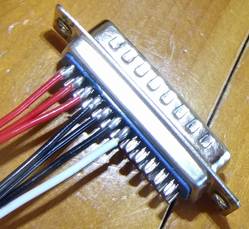
One more photo. I disassembled and reassembled the first connector that I did (more than a week ago). I am much happier with this iteration:
[img]cid:.0[/img]
These wires are for the pitot tube heater. It draws 12 amps so I am using three pins each for power, plus one pin for the status lamp. These three 20 AWG pigtails join to 12 AWG wire which runs the length of the wing.
 These joints look good. I would use 22AWG "ballast
 resistor" pigtails. Here you are actually using
 the wire as a resistor . . . the larger the better
 from the standpoint of sharing loads across an
 array of pins. Also, be aware that the legacy
 heated pitot tubes have a strong temperature
 coefficient. A typical pitot heater for a Beechejt
 is 1.5 ohms at 0C . . . a time when the tube is
 likely to be turned on. 28V/1.5 ohms is 18A start
 up current. When the heater gets to 100C (typical
 high altitude condition) it goes to 2.2 ohms
 for 12.7A running current. 14v probes behave similarly
 at about 2x the current.
 What kind of probe are we talking about?
 If you've lots of unused pins in this connector,
 it wouldn't hurt to use 5 or 6 pins per path
 and I'd certainly drop to 22AWG ballast wires.
 Another thing to consider for the solder-cup
 connector is the form of the female pins in
 the connector . . . not quite as robust and
 uniform their crimp style cousins . . . so
 extra pins if available wouldn't hurt a thing.
 The work we did at Beech was entirely with
 crimped pins. I'm not suggesting that your
 design goals cannot be met with this connector,
 just that I have no experience with the parallel
 pins in the commercial connectors so if there
 are unused pins in the connector, bringing
 them into harness with the three already in
 service is not a bad thing to consider.
 The extra wire is a 'sense' wire? What does
 it do for you?
|
Bob,
I'm glad that those connections look better. The other ones that you criticized were my first two. I'll go back and rework them.
I am planning a Dynon heated pitot tube. Here is my wiring diagram, including the warning lamp:
â
  pitot.pdf  pitot.pdf
âDynon says that that lamp will illuminate if the heater fails.
I have plenty of spare pins in the connector. See my connector "diagram"
â
 wing root connectors.pdf
â
Dynon says 11-12 A for the heater so I planned on 3 pins (at) 5 A per pin.
I'll have to buy some more 22 AWG wire if I am going to switch the ballast wires. Do you see any reason why I cannot buy 22 AWG wire locally (which won't be tefzel insulated) instead of mail ordering a small amount of tefzel wire? I can't think of any reason to prefer one insulation material over another for this application.
Cheers,
  -- Art Z.
--
http://CheerfulCurmudgeon.com/"If I am not for myself, who is for me? And if I am only for myself, what am I? And if not now, when?" Hillel
| | - The Matronics AeroElectric-List Email Forum - | | | Use the List Feature Navigator to browse the many List utilities available such as the Email Subscriptions page, Archive Search & Download, 7-Day Browse, Chat, FAQ, Photoshare, and much more:
http://www.matronics.com/Navigator?AeroElectric-List |
|
| Description: |
|
| Filesize: |
216.87 KB |
| Viewed: |
3649 Time(s) |
|
|
|
| Back to top |
|
 |
nuckolls.bob(at)aeroelect
Guest
|
| Posted: Sun Sep 25, 2016 11:03 am Post subject: Problems Soldering DB-25 Connectors |
|
|
| Quote: |
Bob,
I am using a Weller WES51. I have been setting it at 650 when butt splicing wires and bumped up to 700 degrees for the DB-25 pins. I can certainly try something hotter. I was worried about damaging the connector. |
700 is fine
| Quote: | I have two tips for the iron, the one that came with it and an extra narrow tip that I also bought. I find that extra narrow tip easier to control when working on the DB-25 pins but it doesn't transfer heat as well.
I am using Kester 60/40 solder. |
Okay . . . you're 95% of the way there.
All that's left is to refine your technique.
Bob . . .
| | - The Matronics AeroElectric-List Email Forum - | | | Use the List Feature Navigator to browse the many List utilities available such as the Email Subscriptions page, Archive Search & Download, 7-Day Browse, Chat, FAQ, Photoshare, and much more:
http://www.matronics.com/Navigator?AeroElectric-List |
|
|
|
| Back to top |
|
|
nuckolls.bob(at)aeroelect
Guest
|
| Posted: Sun Sep 25, 2016 12:06 pm Post subject: Problems Soldering DB-25 Connectors |
|
|
| Quote: | | I'll have to buy some more 22 AWG wire if I am going to switch the ballast wires. Do you see any reason why I cannot buy 22 AWG wire locally (which won't be tefzel insulated) instead of mail ordering a small amount of tefzel wire? I can't think of any reason to prefer one insulation material over another for this application. |
I've packaged up enough 22AWG tefzel for this
task. You may have it Tues, Wed for sure.
I'd not kept track of Dynon's product line. Looks
like their pitot tube is electronically controlled
using a technique I proposed to Beech upteen years
ago you duty cycle switch power to the heater
(except that the OFF current is regulated to some
very low value and accurately known). You measure
voltage across the heater during off-time and
you can deduce the heater's present temperature.
I did a bunch of studies on pitot tubes used on
the Beechjet during an analysis of loss of airspeed
events. Turns out that these things are really
easy to regulate by this methodology. I'm guessing
that Dynon has exploited the smart controller's
software to include soft-start during warm-up.
Hence, extra-robust wiring for inrush mitigation
is not necessary. But better ballasting of the
pins . . . and adding some to the mix is not
a bad idea.
Bob . . .
| | - The Matronics AeroElectric-List Email Forum - | | | Use the List Feature Navigator to browse the many List utilities available such as the Email Subscriptions page, Archive Search & Download, 7-Day Browse, Chat, FAQ, Photoshare, and much more:
http://www.matronics.com/Navigator?AeroElectric-List |
|
|
|
| Back to top |
|
|
efraim.otero(at)gmail.com
Guest
|
| Posted: Mon Sep 26, 2016 11:03 am Post subject: Problems Soldering DB-25 Connectors |
|
|
Thanks!! I got a lot to learn!! | Quote: | On Sep 24, 2016, at 5:44 PM, Art Zemon <art(at)zemon.name (art(at)zemon.name)> wrote:
On Sat, Sep 24, 2016 at 2:46 PM, Art Zemon <art(at)zemon.name (art(at)zemon.name)> wrote: | Quote: | On Fri, Sep 23, 2016 at 9:29 AM, Efraim Otero <efraim.otero(at)gmail.com (efraim.otero(at)gmail.com)> wrote: | Quote: | Art:Please send pictures so us newbies can compare⦠thanks for sharing!!
|
Efraim,
Your wish is my command
|
One more photo. I disassembled and reassembled the first connector that I did (more than a week ago). I am much happier with this iteration:
<IMG_20160924_164542.jpg>These wires are for the pitot tube heater. It draws 12 amps so I am using three pins each for power, plus one pin for the status lamp. These three 20 AWG pigtails join to 12 AWG wire which runs the length of the wing.
Cheers,
-- Art Z.
-- http://CheerfulCurmudgeon.com/"If I am not for myself, who is for me? And if I am only for myself, what am I? And if not now, when?" Hillel
|
| | - The Matronics AeroElectric-List Email Forum - | | | Use the List Feature Navigator to browse the many List utilities available such as the Email Subscriptions page, Archive Search & Download, 7-Day Browse, Chat, FAQ, Photoshare, and much more:
http://www.matronics.com/Navigator?AeroElectric-List |
|
|
|
| Back to top |
|
|
ransman
Joined: 08 Aug 2008
Posts: 8
Location: Sweden
|
| Posted: Mon Sep 26, 2016 11:22 am Post subject: Problems Soldering DB-25 Connectors |
|
|
I found a good old method here:
https://www.youtube.com/watch?v=_GLeCt_u3U8
2016-09-22 2:33 GMT+02:00 Art Zemon <art(at)zemon.name (art(at)zemon.name)>:
| Quote: | Folks,
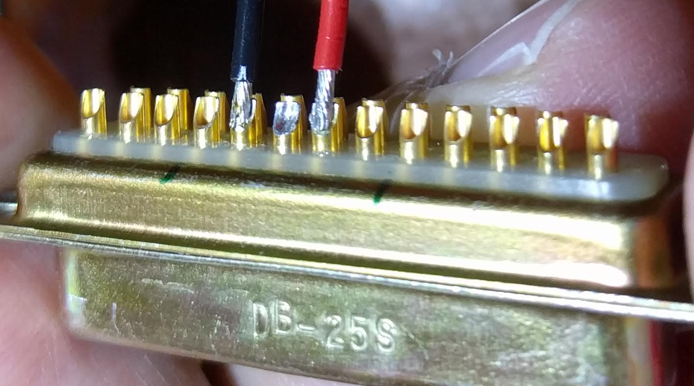
I am trying to solder 20 gauge wire into DB-25 connectors and having a tough time. The conductors just barely fit into the cups on the backs of the pins when everything is "dry," before tinning. After I tin either one, pin or wire, I cannot get all of the conductors into the cup. I end up with something like this:
[img]cid:ii_itdlrj9b0_1574f4d7e91899df[/img]
I'm afraid that those are not acceptable. What do you think?
If they are not acceptable, what is the solution? Can I trim a few conductors away so that the remainder will slip into the cup? Or should I just give up and switch to crimp pins? Or what?
Thanks,
  -- Art Z.
--
http://CheerfulCurmudgeon.com/"If I am not for myself, who is for me? And if I am only for myself, what am I? And if not now, when?" Hillel
|
| | - The Matronics AeroElectric-List Email Forum - | | | Use the List Feature Navigator to browse the many List utilities available such as the Email Subscriptions page, Archive Search & Download, 7-Day Browse, Chat, FAQ, Photoshare, and much more:
http://www.matronics.com/Navigator?AeroElectric-List |
|
| Description: |
|
| Filesize: |
98.2 KB |
| Viewed: |
3624 Time(s) |
|
_________________
"Cum propris suis alis volat"
He flies with his own wings |
|
| Back to top |
|
|
|
|
You cannot post new topics in this forum
You cannot reply to topics in this forum
You cannot edit your posts in this forum
You cannot delete your posts in this forum
You cannot vote in polls in this forum
You cannot attach files in this forum
You can download files in this forum
|
Powered by phpBB © 2001, 2005 phpBB Group
|

