 |
Matronics Email Lists
Web Forum Interface to the Matronics Email Lists
|
| View previous topic :: View next topic |
| Author |
Message |
Eric M. Jones
Joined: 10 Jan 2006
Posts: 565
Location: Massachusetts
|
 Posted: Thu Jan 18, 2018 1:40 pm Post subject: diode on starter contactor Posted: Thu Jan 18, 2018 1:40 pm Post subject: diode on starter contactor |
 |
|
This subject has been discussed here for years.


My opinion and what I have suggested for years is that the current best

practice is to use bidirectional zener diodes. Regular diodes are

problematic. See attached.


You can use what I suggest or slightly heavier ones for better

mechanical properties. (I am currently shipping the 5KE20CA parts).


Eric M. Jones


-Bought a 177RG Cardinal.
| | - The Matronics AeroElectric-List Email Forum - | | | Use the List Feature Navigator to browse the many List utilities available such as the Email Subscriptions page, Archive Search & Download, 7-Day Browse, Chat, FAQ, Photoshare, and much more:
http://www.matronics.com/Navigator?AeroElectric-List |
|
| Description: |
|

Download |
| Filename: |
SnapJacks.pdf |
| Filesize: |
82.17 KB |
| Downloaded: |
604 Time(s) |
_________________
Eric M. Jones
www.PerihelionDesign.com
113 Brentwood Drive
Southbridge, MA 01550
(508) 764-2072
emjones(at)charter.net |
|
| Back to top |
|
 |
alec(at)alecmyers.com
Guest
|
| Posted: Thu Jan 18, 2018 1:56 pm Post subject: diode on starter contactor |
|
|
Eric,


I see great marketing (FUD) in that document but no actual information.

What do you believe to be the problem with a regular diode?


On Jan 18, 2018, at 4:38 PM, Eric Jones <emjones(at)charter.net> wrote:


This subject has been discussed here for years.


My opinion and what I have suggested for years is that the current best practice is to use bidirectional zener diodes. Regular diodes are problematic. See attached.


You can use what I suggest or slightly heavier ones for better mechanical properties. (I am currently shipping the 5KE20CA parts).


Eric M. Jones


-Bought a 177RG Cardinal.


<SnapJacks.pdf>
| | - The Matronics AeroElectric-List Email Forum - | | | Use the List Feature Navigator to browse the many List utilities available such as the Email Subscriptions page, Archive Search & Download, 7-Day Browse, Chat, FAQ, Photoshare, and much more:
http://www.matronics.com/Navigator?AeroElectric-List |
|
|
|
| Back to top |
|
|
kenryan
Joined: 20 Oct 2009
Posts: 429
|
| Posted: Thu Jan 18, 2018 1:56 pm Post subject: diode on starter contactor |
|
|
Eric, is it okay to solder a wire to your snapjacks?
On Thu, Jan 18, 2018 at 12:38 PM, Eric Jones <emjones(at)charter.net (emjones(at)charter.net)> wrote:
| Quote: | This subject has been discussed here for years.
My opinion and what I have suggested for years is that the current best practice is to use bidirectional zener diodes. Regular diodes are problematic. See attached.
You can use what I suggest or slightly heavier ones for better mechanical properties. (I am currently shipping the 5KE20CA parts).
Eric M. Jones
-Bought a 177RG Cardinal.
|
| | - The Matronics AeroElectric-List Email Forum - | | | Use the List Feature Navigator to browse the many List utilities available such as the Email Subscriptions page, Archive Search & Download, 7-Day Browse, Chat, FAQ, Photoshare, and much more:
http://www.matronics.com/Navigator?AeroElectric-List |
|
|
|
| Back to top |
|
|
nuckolls.bob(at)aeroelect
Guest
|
| Posted: Thu Jan 18, 2018 2:01 pm Post subject: diode on starter contactor |
|
|
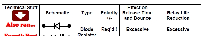
At 03:38 PM 1/18/2018, you wrote:
| Quote: | This subject has been discussed here for years.
My opinion and what I have suggested for years is that the current best practice is to use bidirectional zener diodes. Regular diodes are problematic. See attached. |
[img]cid:7.1.0.9.0.20180118155821.0661d178(at)aeroelectric.com.0[/img]
Can you demonstrate this? "Excessive" is non-quantified.
Was my bench top study flawed in some way?
Bob . . .
| | - The Matronics AeroElectric-List Email Forum - | | | Use the List Feature Navigator to browse the many List utilities available such as the Email Subscriptions page, Archive Search & Download, 7-Day Browse, Chat, FAQ, Photoshare, and much more:
http://www.matronics.com/Navigator?AeroElectric-List |
|
| Description: |
|
| Filesize: |
59.17 KB |
| Viewed: |
16723 Time(s) |
|
|
|
| Back to top |
|
|
alec(at)alecmyers.com
Guest
|
| Posted: Thu Jan 18, 2018 2:39 pm Post subject: diode on starter contactor |
|
|
Iâm trying to work out why a diode has *any* significant effect on release time compared to a tranzorb or similar, and if it did, why you might care.
Also, why should it have any effect on relay life reduction �
My skeptical self needs help to get beyond merely âmore expensive therefore must be betterâ.
On Jan 18, 2018, at 5:01 PM, Robert L. Nuckolls, III <nuckolls.bob(at)aeroelectric.com> wrote:
At 03:38 PM 1/18/2018, you wrote:
| Quote: | This subject has been discussed here for years.
My opinion and what I have suggested for years is that the current best practice is to use bidirectional zener diodes. Regular diodes are problematic. See attached.
|
<f1b501.jpg>
Can you demonstrate this? "Excessive" is non-quantified.
Was my bench top study flawed in some way?
Bob . . .
| | - The Matronics AeroElectric-List Email Forum - | | | Use the List Feature Navigator to browse the many List utilities available such as the Email Subscriptions page, Archive Search & Download, 7-Day Browse, Chat, FAQ, Photoshare, and much more:
http://www.matronics.com/Navigator?AeroElectric-List |
|
|
|
| Back to top |
|
|
user9253
Joined: 28 Mar 2008
Posts: 1969
Location: Riley TWP Michigan
|
| Posted: Thu Jan 18, 2018 4:50 pm Post subject: Re: diode on starter contactor |
|
|
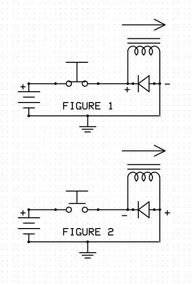
A capacitor opposes any change in voltage.

An inductor (coil) opposes any change in current.

When the switch is closed (Figure 1), positive

current flows from left to right through the coil.

The diode does not conduct because positive

current can not flow against the arrow.

_

When the switch is opened (Figure 2), the

coil opposes any change and tries to

maintain the current.  The coil is no longer a load.

The coil is now a source, like a battery.

Induced current still flows in the same direction

through the coil from left to right.

But the polarity has changed because

because the coil is now a source, not a load.

The diode now conducts because positive on

the right side flows with the arrow.  Current

always tries to return to the source, the coil in

this case.  It takes the path of least resistance,

which is through the diode, not across the open

switch contacts.  The induced voltage is limited

to the forward voltage drop across the diode.
| | - The Matronics AeroElectric-List Email Forum - | | | Use the List Feature Navigator to browse the many List utilities available such as the Email Subscriptions page, Archive Search & Download, 7-Day Browse, Chat, FAQ, Photoshare, and much more:
http://www.matronics.com/Navigator?AeroElectric-List |
|
| Description: |
|
| Filesize: |
68.61 KB |
| Viewed: |
16709 Time(s) |
|
_________________
Joe Gores |
|
| Back to top |
|
|
cluros(at)gmail.com
Guest
|
| Posted: Thu Jan 18, 2018 5:09 pm Post subject: diode on starter contactor |
|
|
Last year I put a lighter AGM battery in my aircraft and moved it to the
firewall along with the master contactor and made some new diodes for the
contactors (one was broken). Saved about 4 pounds in wiring alone! Only
problem afterwards was that if the battery was even slightly down sometimes
the starter would turn a split second and then nothing. Repeated attempts
usually ended up with the starter eventually running fine until the engine
started. Putting a voltmeter on the starter confirmed that the problem was
a lack of power to the starter, not the starter itself. I had a battery
problem later on and replaced the battery, no change. Thinking I had messed
up the starter contactor while tightening nuts on it I swapped it out, no
change. At this point I started to suspect my diode so I disconnected it:
Problem gone! I suspect I installed it backwards. Going to make the new one
with clear shrinkwrap tubing so it can't happen again.
On Thu, Jan 18, 2018 at 2:37 PM, Alec Myers <alec(at)alecmyers.com> wrote:
[quote]
Iâm trying to work out why a diode has *any* significant effect on release
time compared to a tranzorb or similar, and if it did, why you might care
| | - The Matronics AeroElectric-List Email Forum - | | | Use the List Feature Navigator to browse the many List utilities available such as the Email Subscriptions page, Archive Search & Download, 7-Day Browse, Chat, FAQ, Photoshare, and much more:
http://www.matronics.com/Navigator?AeroElectric-List |
|
|
|
| Back to top |
|
|
nuckolls.bob(at)aeroelect
Guest
|
| Posted: Fri Jan 19, 2018 8:00 am Post subject: diode on starter contactor |
|
|
At 04:37 PM 1/18/2018, you wrote:
| Quote: | --> AeroElectric-List message posted by: Alec Myers <alec(at)alecmyers.com>
Iâm trying to work out why a diode has *any* significant effect on release time compared to a tranzorb or similar, and if it did, why you might care.
Also, why should it have any effect on relay life reduction
?
My skeptical self needs help to get beyond merely âmore expensive therefore must be betterâ. |
When mechanical contacts are opened, an electric
arc forms in the air gap. With low voltages and
currents, the fire may be small, but it is never
zero. In one of my articles, I mentioned and experiment
when a microswitch was biased up with a dry cell
and resistor. The contacts were observed
through a microscope in the dark (the side was opened
up on the switch for the experiment).
Even at these very low power levels, a BLUE arc
could be observed. The temperature of blue is
HOT. This suggests that no matter what the power
level, every opening even will transfer molecules
of metal between contacts.
Again, not a lot of metal but never zero.
As energy levels go up and particularly
at higher voltages, the intensity and DURATION
of the arcing event increases. This is an expected
condition. Relays are designed to meet life cycle
ratings at specific power levels and circuit
characteristics by adjusting contact material,
closing forces, opening velocities, opening
gaps, etc. Conditions are important . . . switches
and relays will have AC, DC and LAMP ratings
applied to their service life limits.
https://goo.gl/CPtPYJ
If you've ever tried to do any stick-welding, you
understand the need for (1) making initial cold
contact, (2) breaking that contact to form an
arc, then maintaining an optimum distance between
rod and work-piece to achieve a SUSTAINED fire
at a temperature conducive to the TRANSFER
of metal from rod to work-piece.
If the contacts of a switch or relay do not spread
fast enough, wide enough and with sufficient
thermal mass in contacts, then the TRANSFER of
metal will exceed that which meets design goals
for service life.
This lays the groundwork for a notion that relay
contacts will accelerate open at some rate which is
a function of spring, mass and decay of the
magnetic field which was originally applied to
close the contacts.
It's easily demonstrated that rate of decay for
this magnetic field is strongly influenced by
the choice of suppression for energy stored in
the coil at the time it is de-energized.
A totally open-circuit coil is the fastest, but
transient voltage during field collapse is greatest.
You can drive a coil with a current limited source
and the throw a dead short across the coil, reducing
its excitation current to zero thus initiating
the contact opening sequence. In this condition,
the field collapse transient voltage will be zero
and time to decay will be a whole lot longer.
Hence, there is a range of decay rates offered by
the array of suppression techniques.
I've have yet to discover a paper that describes
the behavior of relay magnetic holding force
in detail . . . many papers that jump to an
'obvious' conclusion that if decay rate in
the coil is extended by factors of 10 or more,
then opening velocity of the contacts is similarly
depressed.
What I observed (in 45 years of herding electrons
in airplanes and conducting numerous relay and
switch failure studies) is that as a relay closes,
the CONTACTS CLOSE before the magnetic armature
BOTTOMS OUT. There is a spring rate associated
with this extra motion that sets the contact
closed holding force.
This leads us to the idea that as the magnetic
field in the device decays, there is a period
of time from first motion the of armature off
the bottomed-out position until closing force
on the contacts drops to zero and they begin
to move. This means that there is a GROWING
AIR GAP in the magnetic circuit holding the
contacts closed.
This air gap has a profound suppressing effect
on that magnetic force. It's an effect that
grossly over-rides the decay rate of the magnetic
from the coil.
Magnetic decay rate does indeed affect drop-out
time for the relay . . . this was demonstrated in
the data collected during my bench-top experiments.
Decay rate adds a time delay between de-energizing
of the coil and first opening of the contacts.
However, by the time the contacts see first motion,
the magnetic air gap is established and growing.
The air gap has much more control over contact
acceleration than does coil current. Hence, the
duration of arc between spreading contacts showed
only a slight difference between diode-suppressed
and non-suppressed contactor.
The case for 'supper suppressors' is further
weakened by the fact that starter and battery
contactors on our airplanes are considered very
busy if they get a few operations per week.
The average light aircraft flies 50 hours
a year. If you install switches and relay rated
for tens of thousands of operations, it stands to
reason that benefits gained by going-the-extra-mile
on coil suppression yields no measurable benefit.
Then, there is the study of contact erosion during
closure as influenced by the physics of the switched
circuit. This is due to arcing that occurs during
contact BOUNCE. Many closures and openings per
operation . . . much smaller gap during the bounce . . .
but exceedingly unfriendly to relay life under
some conditions.
But that's a totally different story . . .
Bob . . .
| | - The Matronics AeroElectric-List Email Forum - | | | Use the List Feature Navigator to browse the many List utilities available such as the Email Subscriptions page, Archive Search & Download, 7-Day Browse, Chat, FAQ, Photoshare, and much more:
http://www.matronics.com/Navigator?AeroElectric-List |
|
|
|
| Back to top |
|
|
nuckolls.bob(at)aeroelect
Guest
|
| Posted: Fri Jan 19, 2018 8:08 am Post subject: diode on starter contactor |
|
|
At 07:09 PM 1/18/2018, you wrote:
| Quote: | | Last year I put a lighter AGM battery in my aircraft and moved it to the firewall along with the master contactor and made some new diodes for the contactors (one was broken). Saved about 4 pounds in wiring alone! Only problem afterwards was that if the battery was even slightly down sometimes the starter would turn a split second and then nothing. Repeated attempts usually ended up with the starter eventually running fine until the engine started. Putting a voltmeter on the starter confirmed that the problem was a lack of power to the starter, not the starter itself. I had a battery problem later on and replaced the battery, no change. Thinking I had messed up the starter contactor while tightening nuts on it I swapped it out, no change. At this point I started to suspect my diode so I disconnected it: Problem gone! I suspect I installed it backwards. Going to make the new one with clear shrinkwrap tubing so it can't happen again. |
If your diode is installed backwards, it will conduct
HARD while the starter button is depressed. Plastic
diodes generally smoke for a few seconds and split,
some will literally explode. I've seen a few cases
where they simply fused short and tripped the starter
control circuit breaker.
If removing the diode cured your problem, then it
probably was 'backwards'. Do you have a breaker
or fuse on your starter control line? That shorted condition
should have opened the circuit protection.
Bob . . .
| | - The Matronics AeroElectric-List Email Forum - | | | Use the List Feature Navigator to browse the many List utilities available such as the Email Subscriptions page, Archive Search & Download, 7-Day Browse, Chat, FAQ, Photoshare, and much more:
http://www.matronics.com/Navigator?AeroElectric-List |
|
|
|
| Back to top |
|
|
kenryan
Joined: 20 Oct 2009
Posts: 429
|
| Posted: Fri Jan 19, 2018 8:45 am Post subject: diode on starter contactor |
|
|
I'm confused. It seems like you are now saying that because the relays are rated for far more cycles than they will ever see, there is no reason to bother with diodes.
Sent from my Android. Sorry Steve.
On Jan 19, 2018 7:06 AM, "Robert L. Nuckolls, III" <nuckolls.bob(at)aeroelectric.com (nuckolls.bob(at)aeroelectric.com)> wrote: | Quote: | At 04:37 PM 1/18/2018, you wrote:
| Quote: | --> AeroElectric-List message posted by: Alec Myers <alec(at)alecmyers.com (alec(at)alecmyers.com)>
Iââ¬â¢m trying to work out why a diode has *any* significant effect on release time compared to a tranzorb or similar, and if it did, why you might care.
Also, why should it have any effect on relay life reduction �
My skeptical self needs help to get beyond merely ââ¬Åmore expensive therefore must be betterâ⬠. |
Â
 When mechanical contacts are opened, an electric
 arc forms in the air gap. With low voltages and
 currents, the fire may be small, but it is never
 zero. In one of my articles, I mentioned and experiment
 when a microswitch was biased up with a dry cell
 and resistor. The contacts were observed
 through a microscope in the dark (the side was opened
 up on the switch for the experiment).
 Even at these very low power levels, a BLUE arc
 could be observed. The temperature of blue is
 HOT. This suggests that no matter what the power
 level, every opening even will transfer molecules
 of metal between contacts.
 Again, not a lot of metal but never zero.
 As energy levels go up and particularly
 at higher voltages, the intensity and DURATION
 of the arcing event increases. This is an expected
 condition. Relays are designed to meet life cycle
 ratings at specific power levels and circuit
 characteristics by adjusting contact material,
 closing forces, opening velocities, opening
 gaps, etc. Conditions are important . . . switches
 and relays will have AC, DC and LAMP ratings
 applied to their service life limits.
https://goo.gl/CPtPYJ
 If you've ever tried to do any stick-welding, you
 understand the need for (1) making initial cold
 contact, (2) breaking that contact to form an
 arc, then maintaining an optimum distance between
 rod and work-piece to achieve a SUSTAINED fire
 at a temperature conducive to the TRANSFER
 of metal from rod to work-piece.
 If the contacts of a switch or relay do not spread
 fast enough, wide enough and with sufficient
 thermal mass in contacts, then the TRANSFER of
 metal will exceed that which meets design goals
 for service life.
 This lays the groundwork for a notion that relay
 contacts will accelerate open at some rate which is
 a function of spring, mass and decay of the
 magnetic field which was originally applied to
 close the contacts.
 It's easily demonstrated that rate of decay for
 this magnetic field is strongly influenced by
 the choice of suppression for energy stored in
 the coil at the time it is de-energized.
 A totally open-circuit coil is the fastest, but
 transient voltage during field collapse is greatest.
 You can drive a coil with a current limited source
 and the throw a dead short across the coil, reducing
 its excitation current to zero thus initiating
 the contact opening sequence. In this condition,
 the field collapse transient voltage will be zero
 and time to decay will be a whole lot longer.
 Hence, there is a range of decay rates offered by
 the array of suppression techniques.
 I've have yet to discover a paper that describes
 the behavior of relay magnetic holding force
 in detail . . . many papers that jump to an
 'obvious' conclusion that if decay rate in
 the coil is extended by factors of 10 or more,
 then opening velocity of the contacts is similarly
 depressed.
 What I observed (in 45 years of herding electrons
 in airplanes and conducting numerous relay and
 switch failure studies) is that as a relay closes,
 the CONTACTS CLOSE before the magnetic armature
 BOTTOMS OUT. There is a spring rate associated
 with this extra motion that sets the contact
 closed holding force.
 This leads us to the idea that as the magnetic
 field in the device decays, there is a period
 of time from first motion the of armature off
 the bottomed-out position until closing force
 on the contacts drops to zero and they begin
 to move. This means that there is a GROWING
 AIR GAP in the magnetic circuit holding the
 contacts closed.
 This air gap has a profound suppressing effect
 on that magnetic force. It's an effect that
 grossly over-rides the decay rate of the magnetic
 from the coil.
 Magnetic decay rate does indeed affect drop-out
 time for the relay . . . this was demonstrated in
 the data collected during my bench-top experiments.
 Decay rate adds a time delay between de-energizing
 of the coil and first opening of the contacts.
 However, by the time the contacts see first motion,
 the magnetic air gap is established and growing.
 The air gap has much more control over contact
 acceleration than does coil current. Hence, the
 duration of arc between spreading contacts showed
 only a slight difference between diode-suppressed
 and non-suppressed contactor.
 The case for 'supper suppressors' is further
 weakened by the fact that starter and battery
 contactors on our airplanes are considered very
 busy if they get a few operations per week.
 The average light aircraft flies 50 hours
 a year. If you install switches and relay rated
 for tens of thousands of operations, it stands to
 reason that benefits gained by going-the-extra-mile
 on coil suppression yields no measurable benefit.
 Then, there is the study of contact erosion during
 closure as influenced by the physics of the switched
 circuit. This is due to arcing that occurs during
 contact BOUNCE. Many closures and openings per
 operation . . . much smaller gap during the bounce . . .
 but exceedingly unfriendly to relay life under
 some conditions.
 But that's a totally different story . . .
Â
 Bob . . .
|
| | - The Matronics AeroElectric-List Email Forum - | | | Use the List Feature Navigator to browse the many List utilities available such as the Email Subscriptions page, Archive Search & Download, 7-Day Browse, Chat, FAQ, Photoshare, and much more:
http://www.matronics.com/Navigator?AeroElectric-List |
|
|
|
| Back to top |
|
|
bob.verwey(at)gmail.com
Guest
|
| Posted: Fri Jan 19, 2018 8:57 am Post subject: diode on starter contactor |
|
|
Does the risk not lie in having contacts that weld together or overheat?
On 19 Jan 2018 6:49 PM, "Ken Ryan" <keninalaska(at)gmail.com (keninalaska(at)gmail.com)> wrote: | Quote: | I'm confused. It seems like you are now saying that because the relays are rated for far more cycles than they will ever see, there is no reason to bother with diodes.
Sent from my Android. Sorry Steve.
On Jan 19, 2018 7:06 AM, "Robert L. Nuckolls, III" <nuckolls.bob(at)aeroelectric.com (nuckolls.bob(at)aeroelectric.com)> wrote: | Quote: | At 04:37 PM 1/18/2018, you wrote:
| Quote: | --> AeroElectric-List message posted by: Alec Myers <alec(at)alecmyers.com (alec(at)alecmyers.com)>
Iââ¬â¢m trying to work out why a diode has *any* significant effect on release time compared to a tranzorb or similar, and if it did, why you might care.
Also, why should it have any effect on relay life reduction �
My skeptical self needs help to get beyond merely ââ¬Åmore expensive therefore must be betterâ⬠. |
Â
 When mechanical contacts are opened, an electric
 arc forms in the air gap. With low voltages and
 currents, the fire may be small, but it is never
 zero. In one of my articles, I mentioned and experiment
 when a microswitch was biased up with a dry cell
 and resistor. The contacts were observed
 through a microscope in the dark (the side was opened
 up on the switch for the experiment).
 Even at these very low power levels, a BLUE arc
 could be observed. The temperature of blue is
 HOT. This suggests that no matter what the power
 level, every opening even will transfer molecules
 of metal between contacts.
 Again, not a lot of metal but never zero.
 As energy levels go up and particularly
 at higher voltages, the intensity and DURATION
 of the arcing event increases. This is an expected
 condition. Relays are designed to meet life cycle
 ratings at specific power levels and circuit
 characteristics by adjusting contact material,
 closing forces, opening velocities, opening
 gaps, etc. Conditions are important . . . switches
 and relays will have AC, DC and LAMP ratings
 applied to their service life limits.
https://goo.gl/CPtPYJ
 If you've ever tried to do any stick-welding, you
 understand the need for (1) making initial cold
 contact, (2) breaking that contact to form an
 arc, then maintaining an optimum distance between
 rod and work-piece to achieve a SUSTAINED fire
 at a temperature conducive to the TRANSFER
 of metal from rod to work-piece.
 If the contacts of a switch or relay do not spread
 fast enough, wide enough and with sufficient
 thermal mass in contacts, then the TRANSFER of
 metal will exceed that which meets design goals
 for service life.
 This lays the groundwork for a notion that relay
 contacts will accelerate open at some rate which is
 a function of spring, mass and decay of the
 magnetic field which was originally applied to
 close the contacts.
 It's easily demonstrated that rate of decay for
 this magnetic field is strongly influenced by
 the choice of suppression for energy stored in
 the coil at the time it is de-energized.
 A totally open-circuit coil is the fastest, but
 transient voltage during field collapse is greatest.
 You can drive a coil with a current limited source
 and the throw a dead short across the coil, reducing
 its excitation current to zero thus initiating
 the contact opening sequence. In this condition,
 the field collapse transient voltage will be zero
 and time to decay will be a whole lot longer.
 Hence, there is a range of decay rates offered by
 the array of suppression techniques.
 I've have yet to discover a paper that describes
 the behavior of relay magnetic holding force
 in detail . . . many papers that jump to an
 'obvious' conclusion that if decay rate in
 the coil is extended by factors of 10 or more,
 then opening velocity of the contacts is similarly
 depressed.
 What I observed (in 45 years of herding electrons
 in airplanes and conducting numerous relay and
 switch failure studies) is that as a relay closes,
 the CONTACTS CLOSE before the magnetic armature
 BOTTOMS OUT. There is a spring rate associated
 with this extra motion that sets the contact
 closed holding force.
 This leads us to the idea that as the magnetic
 field in the device decays, there is a period
 of time from first motion the of armature off
 the bottomed-out position until closing force
 on the contacts drops to zero and they begin
 to move. This means that there is a GROWING
 AIR GAP in the magnetic circuit holding the
 contacts closed.
 This air gap has a profound suppressing effect
 on that magnetic force. It's an effect that
 grossly over-rides the decay rate of the magnetic
 from the coil.
 Magnetic decay rate does indeed affect drop-out
 time for the relay . . . this was demonstrated in
 the data collected during my bench-top experiments.
 Decay rate adds a time delay between de-energizing
 of the coil and first opening of the contacts.
 However, by the time the contacts see first motion,
 the magnetic air gap is established and growing.
 The air gap has much more control over contact
 acceleration than does coil current. Hence, the
 duration of arc between spreading contacts showed
 only a slight difference between diode-suppressed
 and non-suppressed contactor.
 The case for 'supper suppressors' is further
 weakened by the fact that starter and battery
 contactors on our airplanes are considered very
 busy if they get a few operations per week.
 The average light aircraft flies 50 hours
 a year. If you install switches and relay rated
 for tens of thousands of operations, it stands to
 reason that benefits gained by going-the-extra-mile
 on coil suppression yields no measurable benefit.
 Then, there is the study of contact erosion during
 closure as influenced by the physics of the switched
 circuit. This is due to arcing that occurs during
 contact BOUNCE. Many closures and openings per
 operation . . . much smaller gap during the bounce . . .
 but exceedingly unfriendly to relay life under
 some conditions.
 But that's a totally different story . . .
Â
 Bob . . .
|
|
| | - The Matronics AeroElectric-List Email Forum - | | | Use the List Feature Navigator to browse the many List utilities available such as the Email Subscriptions page, Archive Search & Download, 7-Day Browse, Chat, FAQ, Photoshare, and much more:
http://www.matronics.com/Navigator?AeroElectric-List |
|
|
|
| Back to top |
|
|
yellowduckduo(at)gmail.co
Guest
|
| Posted: Fri Jan 19, 2018 9:14 am Post subject: diode on starter contactor |
|
|
For all intents and purposes the diode ONLY protects the switch that
controls the relay.
So it does improve system reliability.
Ken
On 19/01/2018 11:44 AM, Ken Ryan wrote:
| Quote: | I'm confused. It seems like you are now saying that because the relays
are rated for far more cycles than they will ever see, there is no
reason to bother with diodes.
|
| | - The Matronics AeroElectric-List Email Forum - | | | Use the List Feature Navigator to browse the many List utilities available such as the Email Subscriptions page, Archive Search & Download, 7-Day Browse, Chat, FAQ, Photoshare, and much more:
http://www.matronics.com/Navigator?AeroElectric-List |
|
|
|
| Back to top |
|
|
ceengland7(at)gmail.com
Guest
|
| Posted: Fri Jan 19, 2018 9:22 am Post subject: diode on starter contactor |
|
|
I think y'all are a bit confused on what the diodes actually do. The diode across the relay coil is there to protect the controlling *switch's* low current contacts; not the relay contacts. Now, since TANSTAFL (there's no such thing as a free lunch), the downside (of questionable significance) to the diode being in the circuit is that it *can* slow the collapse of the magnetic field in the relay, leading some to think (evidenced by the link to back-to-back zeners) that it puts the *relay* contacts at more risk.
Not to speak for Bob, but his latest post(s) address that slowing of the magnetic field collapse (of questionable significance), and tell us that his testing has shown that with most relays, the contacts don't actually start to separate until after that slowed magnetic field decay isn't having any influence.
So....The bottom line is that the diode *is* needed to protect *switch* contacts, and its presence has *minimal to zero* real world impact on the *relay's* contacts. The takeaway is that you do need the diode, and nothing more elaborate than a standard diode is needed.
Those of us who made our living playing with these components have an easy time seeing what he's describing. It might serve you well to visit some appliance/electrical repair facility & talk them out of a couple of open frame relays so you can play with them & see what he's describing.
On 1/19/2018 10:56 AM, Bob Verwey wrote:
| Quote: | Does the risk not lie in having contacts that weld together or overheat?
On 19 Jan 2018 6:49 PM, "Ken Ryan" <keninalaska(at)gmail.com (keninalaska(at)gmail.com)> wrote: | Quote: | I'm confused. It seems like you are now saying that because the relays are rated for far more cycles than they will ever see, there is no reason to bother with diodes.
Sent from my Android. Sorry Steve.
On Jan 19, 2018 7:06 AM, "Robert L. Nuckolls, III" <nuckolls.bob(at)aeroelectric.com (nuckolls.bob(at)aeroelectric.com)> wrote: | Quote: | At 04:37 PM 1/18/2018, you wrote:
| Quote: | --> AeroElectric-List message posted by: Alec Myers <alec(at)alecmyers.com (alec(at)alecmyers.com)>
Iââ¬â¢m trying to work out why a diode has *any* significant effect on release time compared to a tranzorb or similar, and if it did, why you might care.
Also, why should it have any effect on relay life reduction �
My skeptical self needs help to get beyond merely ââ¬Åmore expensive therefore must be betterâ⬠. |
Â
 When mechanical contacts are opened, an electric
 arc forms in the air gap. With low voltages and
 currents, the fire may be small, but it is never
 zero. In one of my articles, I mentioned and experiment
 when a microswitch was biased up with a dry cell
 and resistor. The contacts were observed
 through a microscope in the dark (the side was opened
 up on the switch for the experiment).
 Even at these very low power levels, a BLUE arc
 could be observed. The temperature of blue is
 HOT. This suggests that no matter what the power
 level, every opening even will transfer molecules
 of metal between contacts.
 Again, not a lot of metal but never zero.
 As energy levels go up and particularly
 at higher voltages, the intensity and DURATION
 of the arcing event increases. This is an expected
 condition. Relays are designed to meet life cycle
 ratings at specific power levels and circuit
 characteristics by adjusting contact material,
 closing forces, opening velocities, opening
 gaps, etc. Conditions are important . . . switches
 and relays will have AC, DC and LAMP ratings
 applied to their service life limits.
https://goo.gl/CPtPYJ
 If you've ever tried to do any stick-welding, you
 understand the need for (1) making initial cold
 contact, (2) breaking that contact to form an
 arc, then maintaining an optimum distance between
 rod and work-piece to achieve a SUSTAINED fire
 at a temperature conducive to the TRANSFER
 of metal from rod to work-piece.
 If the contacts of a switch or relay do not spread
 fast enough, wide enough and with sufficient
 thermal mass in contacts, then the TRANSFER of
 metal will exceed that which meets design goals
 for service life.
 This lays the groundwork for a notion that relay
 contacts will accelerate open at some rate which is
 a function of spring, mass and decay of the
 magnetic field which was originally applied to
 close the contacts.
 It's easily demonstrated that rate of decay for
 this magnetic field is strongly influenced by
 the choice of suppression for energy stored in
 the coil at the time it is de-energized.
 A totally open-circuit coil is the fastest, but
 transient voltage during field collapse is greatest.
 You can drive a coil with a current limited source
 and the throw a dead short across the coil, reducing
 its excitation current to zero thus initiating
 the contact opening sequence. In this condition,
 the field collapse transient voltage will be zero
 and time to decay will be a whole lot longer.
 Hence, there is a range of decay rates offered by
 the array of suppression techniques.
 I've have yet to discover a paper that describes
 the behavior of relay magnetic holding force
 in detail . . . many papers that jump to an
 'obvious' conclusion that if decay rate in
 the coil is extended by factors of 10 or more,
 then opening velocity of the contacts is similarly
 depressed.
 What I observed (in 45 years of herding electrons
 in airplanes and conducting numerous relay and
 switch failure studies) is that as a relay closes,
 the CONTACTS CLOSE before the magnetic armature
 BOTTOMS OUT. There is a spring rate associated
 with this extra motion that sets the contact
 closed holding force.
 This leads us to the idea that as the magnetic
 field in the device decays, there is a period
 of time from first motion the of armature off
 the bottomed-out position until closing force
 on the contacts drops to zero and they begin
 to move. This means that there is a GROWING
 AIR GAP in the magnetic circuit holding the
 contacts closed.
 This air gap has a profound suppressing effect
 on that magnetic force. It's an effect that
 grossly over-rides the decay rate of the magnetic
 from the coil.
 Magnetic decay rate does indeed affect drop-out
 time for the relay . . . this was demonstrated in
 the data collected during my bench-top experiments.
 Decay rate adds a time delay between de-energizing
 of the coil and first opening of the contacts.
 However, by the time the contacts see first motion,
 the magnetic air gap is established and growing.
 The air gap has much more control over contact
 acceleration than does coil current. Hence, the
 duration of arc between spreading contacts showed
 only a slight difference between diode-suppressed
 and non-suppressed contactor.
 The case for 'supper suppressors' is further
 weakened by the fact that starter and battery
 contactors on our airplanes are considered very
 busy if they get a few operations per week.
 The average light aircraft flies 50 hours
 a year. If you install switches and relay rated
 for tens of thousands of operations, it stands to
 reason that benefits gained by going-the-extra-mile
 on coil suppression yields no measurable benefit.
 Then, there is the study of contact erosion during
 closure as influenced by the physics of the switched
 circuit. This is due to arcing that occurs during
 contact BOUNCE. Many closures and openings per
 operation . . . much smaller gap during the bounce . . .
 but exceedingly unfriendly to relay life under
 some conditions.
 But that's a totally different story . . .
Â
 Bob . . .
|
|
|
 Virus-free. www.avast.com [url=#DAB4FAD8-2DD7-40BB-A1B8-4E2AA1F9FDF2] [/url] Virus-free. www.avast.com [url=#DAB4FAD8-2DD7-40BB-A1B8-4E2AA1F9FDF2] [/url]
| | - The Matronics AeroElectric-List Email Forum - | | | Use the List Feature Navigator to browse the many List utilities available such as the Email Subscriptions page, Archive Search & Download, 7-Day Browse, Chat, FAQ, Photoshare, and much more:
http://www.matronics.com/Navigator?AeroElectric-List |
|
|
|
| Back to top |
|
|
Eric M. Jones
Joined: 10 Jan 2006
Posts: 565
Location: Massachusetts
|
| Posted: Fri Jan 19, 2018 9:42 am Post subject: diode on starter contactor |
|
|
I am reluctant to get into another long discussion on the subject of

coil suppression but I encourage Googling the various extensive

resources on this subject.


Note that there are many techniques tuned to specific application on

this subject, but three things are true:


1) The use of a simple diode is contraindicated.


2) The use of a simple bidirectional zener is a good way to go.


3) MOVs are a good way to go, but they have a discrete lifetime...I was

never comfortable with that. MOVs are usually what fails in

surge-suppression computer multi-outlets.


One COULD use a zener and a regular diode in series, but a bidirectional

zener is polarity insensitive and stone simple.


Kilovac and Gigavac both use bidirectional zeners inside their

contactors for coil supression. What does these people know that you don't?


Eric
| | - The Matronics AeroElectric-List Email Forum - | | | Use the List Feature Navigator to browse the many List utilities available such as the Email Subscriptions page, Archive Search & Download, 7-Day Browse, Chat, FAQ, Photoshare, and much more:
http://www.matronics.com/Navigator?AeroElectric-List |
|
_________________
Eric M. Jones
www.PerihelionDesign.com
113 Brentwood Drive
Southbridge, MA 01550
(508) 764-2072
emjones(at)charter.net |
|
| Back to top |
|
|
kenryan
Joined: 20 Oct 2009
Posts: 429
|
| Posted: Fri Jan 19, 2018 10:03 am Post subject: diode on starter contactor |
|
|
Thanks Charlie. That does clear things up for me as to what Bob was saying.
I am no longer confused (temporary condition I am sure).
Sent from my Android. Sorry Steve.
On Jan 19, 2018 8:26 AM, "Charlie England" <ceengland7(at)gmail.com> wrote:
[quote] I think y'all are a bit confused on what the diodes actually do. The diode
across the relay coil is there to protect the controlling *switch's* low
current contacts; not the relay contacts. Now, since TANSTAFL (there's no
such thing as a free lunch), the downside (of questionable significance)
to the diode being in the circuit is that it *can* slow the collapse of the
magnetic field in the relay, leading some to think (evidenced by the link
to back-to-back zeners) that it puts the *relay* contacts at more risk.
Not to speak for Bob, but his latest post(s) address that slowing of the
magnetic field collapse (of questionable significance), and tell us that
his testing has shown that with most relays, the contacts don't actually
start to separate until after that slowed magnetic field decay isn't having
any influence.
So....The bottom line is that the diode *is* needed to protect *switch*
contacts, and its presence has *minimal to zero* real world impact on the
*relay's* contacts. The takeaway is that you do need the diode, and nothing
more elaborate than a standard diode is needed.
Those of us who made our living playing with these components have an easy
time seeing what he's describing. It might serve you well to visit some
appliance/electrical repair facility & talk them out of a couple of open
frame relays so you can play with them & see what he's describing.
On 1/19/2018 10:56 AM, Bob Verwey wrote:
Does the risk not lie in having contacts that weld together or overheat?
On 19 Jan 2018 6:49 PM, "Ken Ryan" <keninalaska(at)gmail.com> wrote:
> I'm confused. It seems like you are now saying that because the relays
> are rated for far more cycles than they will ever see, there is no reason
> to bother with diodes.
>
> Sent from my Android. Sorry Steve.
>
> On Jan 19, 2018 7:06 AM, "Robert L. Nuckolls, III" <
> nuckolls.bob(at)aeroelectric.com> wrote:
>
>> At 04:37 PM 1/18/2018, you wrote:
>>
>>
>>
>> Iââ¬â¢m trying to work out why a diode has *any* significant effect on
>> release time compared to a tranzorb or similar, and if it did, why you
>> might care.
>> Also, why should it have any effect on relay life reduction �
>> My skeptical self needs help to get beyond merely ââ¬Åmore expensive
>> therefore must be betterâ⬠.
>>
>>
>>
>> When mechanical contacts are opened, an electric
>> arc forms in the air gap. With low voltages and
>> currents, the fire may be small, but it is never
>> zero. In one of my articles, I mentioned and experiment
>> when a microswitch was biased up with a dry cell
>> and resistor. The contacts were observed
>> through a microscope in the dark (the side was opened
>> up on the switch for the experiment).
>>
>> Even at these very low power levels, a BLUE arc
>> could be observed. The temperature of blue is
>> HOT. This suggests that no matter what the power
>> level, every opening even will transfer molecules
>> of metal between contacts.
>>
>> Again, not a lot of metal but never zero.
>>
>> As energy levels go up and particularly
>> at higher voltages, the intensity and DURATION
>> of the arcing event increases. This is an expected
>> condition. Relays are designed to meet life cycle
>> ratings at specific power levels and circuit
>> characteristics by adjusting contact material,
>> closing forces, opening velocities, opening
>> gaps, etc. Conditions are important . . . switches
>> and relays will have AC, DC and LAMP ratings
>> applied to their service life limits.
>>
>> https://goo.gl/CPtPYJ
>>
>> If you've ever tried to do any stick-welding, you
>> understand the need for (1) making initial cold
>> contact, (2) breaking that contact to form an
>> arc, then maintaining an optimum distance between
>> rod and work-piece to achieve a SUSTAINED fire
>> at a temperature conducive to the TRANSFER
>> of metal from rod to work-piece.
>>
>> If the contacts of a switch or relay do not spread
>> fast enough, wide enough and with sufficient
>> thermal mass in contacts, then the TRANSFER of
>> metal will exceed that which meets design goals
>> for service life.
>>
>> This lays the groundwork for a notion that relay
>> contacts will accelerate open at some rate which is
>> a function of spring, mass and decay of the
>> magnetic field which was originally applied to
>> close the contacts.
>>
>> It's easily demonstrated that rate of decay for
>> this magnetic field is strongly influenced by
>> the choice of suppression for energy stored in
>> the coil at the time it is de-energized.
>>
>> A totally open-circuit coil is the fastest, but
>> transient voltage during field collapse is greatest.
>> You can drive a coil with a current limited source
>> and the throw a dead short across the coil, reducing
>> its excitation current to zero thus initiating
>> the contact opening sequence. In this condition,
>> the field collapse transient voltage will be zero
>> and time to decay will be a whole lot longer.
>> Hence, there is a range of decay rates offered by
>> the array of suppression techniques.
>>
>> I've have yet to discover a paper that describes
>> the behavior of relay magnetic holding force
>> in detail . . . many papers that jump to an
>> 'obvious' conclusion that if decay rate in
>> the coil is extended by factors of 10 or more,
>> then opening velocity of the contacts is similarly
>> depressed.
>>
>> What I observed (in 45 years of herding electrons
>> in airplanes and conducting numerous relay and
>> switch failure studies) is that as a relay closes,
>> the CONTACTS CLOSE before the magnetic armature
>> BOTTOMS OUT. There is a spring rate associated
>> with this extra motion that sets the contact
>> closed holding force.
>>
>> This leads us to the idea that as the magnetic
>> field in the device decays, there is a period
>> of time from first motion the of armature off
>> the bottomed-out position until closing force
>> on the contacts drops to zero and they begin
>> to move. This means that there is a GROWING
>> AIR GAP in the magnetic circuit holding the
>> contacts closed.
>>
>> This air gap has a profound suppressing effect
>> on that magnetic force. It's an effect that
>> grossly over-rides the decay rate of the magnetic
>> from the coil.
>>
>> Magnetic decay rate does indeed affect drop-out
>> time for the relay . . . this was demonstrated in
>> the data collected during my bench-top experiments.
>> Decay rate adds a time delay between de-energizing
>> of the coil and first opening of the contacts.
>> However, by the time the contacts see first motion,
>> the magnetic air gap is established and growing.
>>
>> The air gap has much more control over contact
>> acceleration than does coil current. Hence, the
>> duration of arc between spreading contacts showed
>> only a slight difference between diode-suppressed
>> and non-suppressed contactor.
>>
>> The case for 'supper suppressors' is further
>> weakened by the fact that starter and battery
>> contactors on our airplanes are considered very
>> busy if they get a few operations per week.
>> The average light aircraft flies 50 hours
>> a year. If you install switches and relay rated
>> for tens of thousands of operations, it stands to
>> reason that benefits gained by going-the-extra-mile
>> on coil suppression yields no measurable benefit.
>>
>> Then, there is the study of contact erosion during
>> closure as influenced by the physics of the switched
>> circuit. This is due to arcing that occurs during
>> contact BOUNCE. Many closures and openings per
>> operation . . . much smaller gap during the bounce . . .
>> but exceedingly unfriendly to relay life under
>> some conditions.
>>
>> But that's a totally different story . . .
>>
>>
>>
>>
>> Bob . . .
>>
>
<https://www.avast.com/sig-email?utm_medium=email&utm_source=link&utm_campaign=sig-email&utm_content=emailclient&utm_term=icon> Virus-free
| | - The Matronics AeroElectric-List Email Forum - | | | Use the List Feature Navigator to browse the many List utilities available such as the Email Subscriptions page, Archive Search & Download, 7-Day Browse, Chat, FAQ, Photoshare, and much more:
http://www.matronics.com/Navigator?AeroElectric-List |
|
|
|
| Back to top |
|
|
nuckolls.bob(at)aeroelect
Guest
|
| Posted: Fri Jan 19, 2018 10:32 am Post subject: diode on starter contactor |
|
|
At 10:44 AM 1/19/2018, you wrote:
| Quote: | | I'm confused. It seems like you are now saying that because the relays are rated for far more cycles than they will ever see, there is no reason to bother with diodes. |
No . . . .
I am saying that 'optimized' coil spike suppression
has a perhaps a tiny benefit for contactors in
heavy usage applications and no benefit in our
airplanes (very low duty).
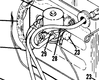
Spike suppression is (and always has been) indicated
for enhancing LIFE OF THE DEVICE THAT CONTROLS
the contactor. E.g. AD against key-switch. The
plain-vanilla diodes have been installed on TC aircraft
for decades. See item 29 in screenshot of 1969
C172 service manual. Couldn't put my hands on my
copy of the Beechjet manual . . . but the little
critters are sprinkled about that airplane as well.
[img]cid:.0[/img]
The diode has (1) no practical effect on service life
of contactor and (2) demonstrable benefit on service life
of the controlling switch . . .
Bob . . .
| | - The Matronics AeroElectric-List Email Forum - | | | Use the List Feature Navigator to browse the many List utilities available such as the Email Subscriptions page, Archive Search & Download, 7-Day Browse, Chat, FAQ, Photoshare, and much more:
http://www.matronics.com/Navigator?AeroElectric-List |
|
| Description: |
|
| Filesize: |
77.81 KB |
| Viewed: |
16691 Time(s) |
|
|
|
| Back to top |
|
|
nuckolls.bob(at)aeroelect
Guest
|
| Posted: Fri Jan 19, 2018 10:43 am Post subject: diode on starter contactor |
|
|
At 10:56 AM 1/19/2018, you wrote:
| Quote: | | Does the risk not lie in having contacts that weld together or overheat? |
Contacts 'weld' on closure. The risk of welding
begins with deformation of contact surfaces due
to combinations of age and service conditions (extra
ordinary inrush current), low energizing current.
Contact welding can also be a function of unanticipated
behaviors due to aircraft wiring. See this study on
'sticking' roll trim relays on the Beechjet:
https://goo.gl/QcfSYo
Spike suppression on the at-risk relay/contactor
has no effect on conditions that promote contact
sticking/welding.
'Overheating' contacts are either too small for
the service or so badly worn as to degrade
conductivity across the contacts.
https://goo.gl/1BJP7y
Note that this victim of severe overheat still
carries remains of its coil suppression diode.
This contactor was used to control power to a
3 horsepower, 28v motor used in the air conditioning
system of a King Air. The diode was there . . .
but the contactor simply got 'tired'.
Bob . . .
| | - The Matronics AeroElectric-List Email Forum - | | | Use the List Feature Navigator to browse the many List utilities available such as the Email Subscriptions page, Archive Search & Download, 7-Day Browse, Chat, FAQ, Photoshare, and much more:
http://www.matronics.com/Navigator?AeroElectric-List |
|
|
|
| Back to top |
|
|
nuckolls.bob(at)aeroelect
Guest
|
| Posted: Fri Jan 19, 2018 10:53 am Post subject: diode on starter contactor |
|
|
| Quote: |
Kilovac and Gigavac both use bidirectional zeners inside their contactors for coil supression. What does these people know that you don't? |
Not a thing I can see . . . the bidirectional zener
performs as advertised. No reason to avoid it or to change
it out in favor of an alternative.
By the same token, there's no demonstrable benefit
for any extra effort to steer clear of
the lowly diode that has also performed as advertised
in literally billions of applications for a
very long time.
My complaint is with publications that make
sweeping assertions that are demonstrably
short on physical evidence or experimental
confirmation.
Bob . . .
| | - The Matronics AeroElectric-List Email Forum - | | | Use the List Feature Navigator to browse the many List utilities available such as the Email Subscriptions page, Archive Search & Download, 7-Day Browse, Chat, FAQ, Photoshare, and much more:
http://www.matronics.com/Navigator?AeroElectric-List |
|
|
|
| Back to top |
|
|
cluros(at)gmail.com
Guest
|
| Posted: Fri Jan 19, 2018 7:13 pm Post subject: diode on starter contactor |
|
|
I was wondering the same thing Bob so I had a look, no fuse or breaker in that line. I guess the builder thought it didn't need one since it connects to ground 8(. I think I should install an inline fuse?
Thank you,
Sebastien
On Fri, Jan 19, 2018 at 8:07 AM, Robert L. Nuckolls, III <nuckolls.bob(at)aeroelectric.com (nuckolls.bob(at)aeroelectric.com)> wrote:
| Quote: | At 07:09 PM 1/18/2018, you wrote:
| Quote: | | Last year I put a lighter AGM battery in my aircraft and moved it to the firewall along with the master contactor and made some new diodes for the contactors (one was broken). Saved about 4 pounds in wiring alone! Only problem afterwards was that if the battery was even slightly down sometimes the starter would turn a split second and then nothing. Repeated attempts usually ended up with the starter eventually running fine until the engine started. Putting a voltmeter on the starter confirmed that the problem was a lack of power to the starter, not the starter itself. I had a battery problem later on and replaced the battery, no change. Thinking I had messed up the starter contactor while tightening nuts on it I swapped it out, no change. At this point I started to suspect my diode so I disconnected it: Problem gone! I suspect I installed it backwards. Going to make the new one with clear shrinkwrap tubing so it can't happen again. |
  If your diode is installed backwards, it will conduct
  HARD while the starter button is depressed. Plastic
  diodes generally smoke for a few seconds and split,
  some will literally explode. I've seen a few cases
  where they simply fused short and tripped the starter
  control circuit breaker.
  If removing the diode cured your problem, then it
  probably was 'backwards'. Do you have a breaker
  or fuse on your starter control line? That shorted condition
  should have opened the circuit protection.
 Bob . . .
|
| | - The Matronics AeroElectric-List Email Forum - | | | Use the List Feature Navigator to browse the many List utilities available such as the Email Subscriptions page, Archive Search & Download, 7-Day Browse, Chat, FAQ, Photoshare, and much more:
http://www.matronics.com/Navigator?AeroElectric-List |
|
|
|
| Back to top |
|
|
nuckolls.bob(at)aeroelect
Guest
|
| Posted: Sat Jan 20, 2018 6:50 am Post subject: diode on starter contactor |
|
|
At 09:12 PM 1/19/2018, you wrote:
| Quote: | | I was wondering the same thing Bob so I had a look, no fuse or breaker in that line. I guess the builder thought it didn't need one since it connects to ground 8(. I think I should install an inline fuse? |
Not sure which 'same thing' you're citing . . .
Fuse in which line, bust thru starter button to starer contactor
or battery to starter contactor?
The CONTROL line from bus to starter switch is
classically protected. No protection is indicated
for the cranking current feeder from battery to
starter contactor.
Suggest you browse the various power distribution
diagrams (Z-figures) at https://goo.gl/kovZJX
While these cover a broad range of applications,
there are features common to all of them that
illustrate both legacy and modern but field
proven techniques for architecture.
Bob . . .
| | - The Matronics AeroElectric-List Email Forum - | | | Use the List Feature Navigator to browse the many List utilities available such as the Email Subscriptions page, Archive Search & Download, 7-Day Browse, Chat, FAQ, Photoshare, and much more:
http://www.matronics.com/Navigator?AeroElectric-List |
|
|
|
| Back to top |
|
|
|
|
You cannot post new topics in this forum
You cannot reply to topics in this forum
You cannot edit your posts in this forum
You cannot delete your posts in this forum
You cannot vote in polls in this forum
You cannot attach files in this forum
You can download files in this forum
|
Powered by phpBB © 2001, 2005 phpBB Group
|

