 |
Matronics Email Lists
Web Forum Interface to the Matronics Email Lists
|
| View previous topic :: View next topic |
| Author |
Message |
woxofswa
Joined: 12 Aug 2008
Posts: 349
Location: AZ
|
 Posted: Fri Sep 21, 2018 1:22 pm Post subject: Alternator/shunt question Posted: Fri Sep 21, 2018 1:22 pm Post subject: Alternator/shunt question |
 |
|
Question. If I run a 30amp backup alternator through the same shunt (Dynon) as the primary 60 amp alternator., mating at the shunt entry and sharing the single cable at the shunt exit (wired as a battery load meter) ...
When the primary is offline, would the amp draw shown for the backup alternator be reasonably correct or would it show artificially low? Would itâs own distinct shunt be required give an accurate measurement of alternator output?
I guess what Iâm asking is, does a shunt have to be matched by amp level to be accurate or can it be oversized?
Thanks in advance.
| | - The Matronics AeroElectric-List Email Forum - | | | Use the List Feature Navigator to browse the many List utilities available such as the Email Subscriptions page, Archive Search & Download, 7-Day Browse, Chat, FAQ, Photoshare, and much more:
http://www.matronics.com/Navigator?AeroElectric-List |
|
_________________
Myron Nelson
Mesa, AZ
Flew May 10 2014 |
|
| Back to top |
|
 |
user9253
Joined: 28 Mar 2008
Posts: 1969
Location: Riley TWP Michigan
|
| Posted: Sat Sep 22, 2018 5:55 am Post subject: Re: Alternator/shunt question |
|
|
Yes, the ammeter will display reasonably correct.  Look at it this way:

Even though the main alternator is rated for 60 amps, most of the time it is only putting out about half of its capacity.  The shunt will not know which alternator is sending 30 amps through it.  The load determines the current, not the alternator.

  Shunts have been known to fail, usually because of a loose connection that makes heat.
| | - The Matronics AeroElectric-List Email Forum - | | | Use the List Feature Navigator to browse the many List utilities available such as the Email Subscriptions page, Archive Search & Download, 7-Day Browse, Chat, FAQ, Photoshare, and much more:
http://www.matronics.com/Navigator?AeroElectric-List |
|
_________________
Joe Gores |
|
| Back to top |
|
|
nuckolls.bob(at)aeroelect
Guest
|
| Posted: Sat Sep 22, 2018 8:51 am Post subject: Alternator/shunt question |
|
|
At 04:22 PM 9/21/2018, you wrote:
| Quote: | --> AeroElectric-List message posted by: "woxofswa" <woxof(at)aol.com>
Question. If I run a 30amp backup alternator through the same shunt (Dynon) as the primary 60 amp alternator., mating at the shunt entry and sharing the single cable at the shunt exit (wired as a battery load meter) ...
|
You can run as many wires as you like
through a current sensor. The instrument
reading the current sensor will display
the SUM of the currents in all wires.
So, if two alternator b-leads share the
same sensor, then the instrument displays
only the operative alternator -OR- the
sum of their efforts depending if they
are both ON.
However, b-lead monitoring of the alternators
is NOT a battery load meter.
Know that an ammeter is NOT generally considered
a systems management tool for flight ops. It's
a diagnostic tool that will sometime yield useful
information . . . ON THE GROUND for chasing and
subduing electro-gremlins.
But it's important to know the significance of
the displayed current reading. If only b-leads
traverse the sensor, then you will never see
the minus-zero-plus readings reminiscent of
the legacy automotive ammeters popularized by
Henry Ford and contemporaries.
Battery ammeter readings are not definitive
indicators of system performance and not recommended
for new construction.
| Quote: | | When the primary is offline, would the amp draw shown for the backup alternator be reasonably correct or would it show artificially low? Would itâs own distinct shunt be required give an accurate measurement of alternator output? |
The Dynon display for current will be as accurate
as the instrument's designed capability irrespective of
how many signal sources are being impressed on the
sensor.
The most useful indicator of system
performance is the voltmeter . . . which is
easily augmented by ACTIVE NOTIFICATION OF
LOW VOLTAGE . . . your first lines of defense
against the dark-panel syndrome.
Bob . . .
| | - The Matronics AeroElectric-List Email Forum - | | | Use the List Feature Navigator to browse the many List utilities available such as the Email Subscriptions page, Archive Search & Download, 7-Day Browse, Chat, FAQ, Photoshare, and much more:
http://www.matronics.com/Navigator?AeroElectric-List |
|
|
|
| Back to top |
|
|
woxofswa
Joined: 12 Aug 2008
Posts: 349
Location: AZ
|
| Posted: Sat Sep 22, 2018 11:04 am Post subject: Re: Alternator/shunt question |
|
|
Thanks for the responses. Let me break the scenario down further.
I recently installed the B&C 30 amp backup alternator.
On my first longish flight to test the system I flew with basic essentials running at 2500 rpm. Turning off both alternators, my ammeter read minus (-9) Amps at 12.5 volts. Turning on the standby alternator, the ammeter showed minus (-2) amps at 12.9 volts which stayed more or less constant for several minutes.
Obviously the backup is producing power, it just doesnât seem to be producing as much as I was expecting at what looks to me to be about 7 Amps. What I am trying to determine is if it is a low production issue, false indication issue, or a misinterpretation of correct indications.
| | - The Matronics AeroElectric-List Email Forum - | | | Use the List Feature Navigator to browse the many List utilities available such as the Email Subscriptions page, Archive Search & Download, 7-Day Browse, Chat, FAQ, Photoshare, and much more:
http://www.matronics.com/Navigator?AeroElectric-List |
|
_________________
Myron Nelson
Mesa, AZ
Flew May 10 2014 |
|
| Back to top |
|
|
nuckolls.bob(at)aeroelect
Guest
|
| Posted: Sat Sep 22, 2018 2:22 pm Post subject: Alternator/shunt question |
|
|
At 02:04 PM 9/22/2018, you wrote:
| Quote: | --> AeroElectric-List message posted by: "woxofswa" <woxof(at)aol.com>
Thanks for the responses. Let me break the scenario down further.
I recently installed the B&C 30 amp backup alternator.
On my first longish flight to test the system I flew with basic essentials running at 2500 rpm. Turning off both alternators, my ammeter read minus (-9) Amps at 12.5 volts. Turning on the standby alternator, the ammeter showed minus (-2) amps at 12.9 volts which stayed more or less constant for several minutes.
Obviously the backup is producing power, it just doesnât seem to be producing as much as I was expecting at what looks to me to be about 7 Amps. What I am trying to determine is if it is a low production issue, false indication issue, or a misinterpretation of correct indications. |
If your ammeter does indeed produce minus readings
with the alternator(s) OFF, then it is indeed
wired as a battery ammeter and should have NO
b-lead wires running through it.
If the standby alternator boosts the bus voltage
to something greater than 13.5 volts, then it
is carrying ALL system loads and perhaps adding
a bit to recharging the battery.
If this condition is true, then the alternator
is just fine irrespective of what the b-lead
current might be.
An alternator under regulation will deliver
no more current than the system demands of it.
B-lead current will be electro-whizzie demands
added to battery demands . . . and could
be quite low. If your bus voltage is correct,
then the alternator is fine.
Can you publish a schematic of how the current
sensor is installed in your system?
Bob . . .
| | - The Matronics AeroElectric-List Email Forum - | | | Use the List Feature Navigator to browse the many List utilities available such as the Email Subscriptions page, Archive Search & Download, 7-Day Browse, Chat, FAQ, Photoshare, and much more:
http://www.matronics.com/Navigator?AeroElectric-List |
|
|
|
| Back to top |
|
|
user9253
Joined: 28 Mar 2008
Posts: 1969
Location: Riley TWP Michigan
|
| Posted: Sat Sep 22, 2018 6:22 pm Post subject: Re: Alternator/shunt question |
|
|
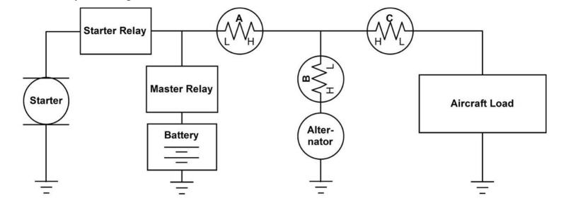
Myron, based on your description, I agree that the aux alternator is putting out 7 amps.  Perhaps the alternator is not spinning fast enough to generate its rated capacity.

  Looking at the attached picture from a Dynon manual, confirm that the shunt is in location A, and not B or C.
| | - The Matronics AeroElectric-List Email Forum - | | | Use the List Feature Navigator to browse the many List utilities available such as the Email Subscriptions page, Archive Search & Download, 7-Day Browse, Chat, FAQ, Photoshare, and much more:
http://www.matronics.com/Navigator?AeroElectric-List |
|
| Description: |
|
| Filesize: |
23.19 KB |
| Viewed: |
27302 Time(s) |
|
_________________
Joe Gores |
|
| Back to top |
|
|
nuckolls.bob(at)aeroelect
Guest
|
| Posted: Sun Sep 23, 2018 9:36 am Post subject: Alternator/shunt question |
|
|
At 09:22 PM 9/22/2018, you wrote:
| Quote: | --> AeroElectric-List message posted by: "user9253" <fransew(at)gmail.com>
Myron, based on your description, I agree that the aux alternator is putting out 7 amps. Perhaps the alternator is not spinning fast enough to generate its rated capacity.
Looking at the attached picture from a Dynon manual, confirm that the shunt is in location A, and not B or C.
--------
Joe Gores
|
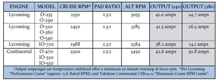
Do I assume correctly that we're talking about a
BC-462 alternator? Referring to B&C published data . . .
[img]cid:7.1.0.9.0.20180923122834.05fbf240(at)aeroelectric.com.0[/img]
. . . the alternator is capable of at least 40A of
output at nominal cruise rpms on any engine. Assuming
that your current sensor is indeed installed as
a battery ammeter -and- you're seeing -2A with the
standby alternator ON, then we have to deduce that
your bus voltage under this test condition is WAaayyyy
too low . . . the battery is still supply a portion of
the ship's running loads.
You did not mention any observed voltage readings and
as Joe suggests it would be helpful to confirm the
actual location of your Dynon sensor in the system.
What votlage regulator are you using on the standby
alternator? Adjustable? Was it checked and adjusted as
necessary at time of installation?
Bob . . .
| | - The Matronics AeroElectric-List Email Forum - | | | Use the List Feature Navigator to browse the many List utilities available such as the Email Subscriptions page, Archive Search & Download, 7-Day Browse, Chat, FAQ, Photoshare, and much more:
http://www.matronics.com/Navigator?AeroElectric-List |
|
| Description: |
|
| Filesize: |
133.4 KB |
| Viewed: |
27279 Time(s) |
|
|
|
| Back to top |
|
|
BARRY CHECK 6
Joined: 15 Mar 2011
Posts: 738
|
| Posted: Sun Sep 23, 2018 10:01 am Post subject: Alternator/shunt question |
|
|
On Sat, Sep 22, 2018 at 6:28 PM Robert L. Nuckolls, III <nuckolls.bob(at)aeroelectric.com (nuckolls.bob(at)aeroelectric.com)> wrote:
| Quote: | At 02:04 PM 9/22/2018, you wrote:
| Quote: | --> AeroElectric-List message posted by: "woxofswa" <woxof(at)aol.com (woxof(at)aol.com)>
Thanks for the responses. Let me break the scenario down further.
I recently installed the B&C 30 amp backup alternator.
On my first longish flight to test the system I flew with basic essentials running at 2500 rpm. Turning off both alternators, my ammeter read minus (-9) Amps at 12.5 volts. |
|
Barry - That indicates your system load is 9 Amps.Â
| Quote: | | Quote: | Turning on the standby alternator, the ammeter showed minus (-2) amps at 12.9 volts which stayed more or less constant for several minutes.
|
|
Barry - Here there are a few items and questions:
9 Amps - 2 Amps = 7 Amps
That indicated the Standby Alt is supplying 7 Amps to the electrical system load.
Which is what the LOAD is!
Question:Â So, why is the LOAD without both alternators off Higher than the Load with one alternator?
Question: Why do you say : "... 12.9 volts which stayed more or less constant for several minutes."?
Are you referring to the voltage and the subsequent drop from 12.9 to 12.5 VDC?
If so, then the backup alternator is NOT putting out the required voltage.
The 12.5 VDC on the load is LOW as you require 13.8 - 14.2 VDC to charge a battery.
What should have been your next TEST would be to:
Shut off the Stand-by Alt and turn on the Main Alt.
IF the VOLTAGE from the Main Alt was 13.8 to 14.2 VDC then you can say the output of the Main Alt is correct.
Follow that up with:Â What is the Indicated Current draw with the Main Alt?
IF the Main Alt is putting out the proper power you should see 9 Amps being supplied to the electrical Load for the Same Configuration as you checked things previously.
Another very simple test would be to disconnect one lead from the battery and hook an Ammeter in series. Use a good digital Ammeter and see what the current draw is. For the same configuration as in your test it should be no less than the 9 Amps. Slightly more when the engine is running due to the extra draw of the NON PM Alt's FIELD.
| Quote: | | Quote: | | Obviously the backup is producing power, it just doesnââ¬â¢t seem to be producing as much as I was expecting at what looks to me to be about 7 Amps. What I am trying to determine is if it is a low production issue, false indication issue, or a misinterpretation of correct indications. |
|
Barry - If you do the above testing, the answer to this question will present itself.
Best of luck,
BarryÂ
| Quote: |
 If your ammeter does indeed produce minus readings
 with the alternator(s) OFF, then it is indeed
 wired as a battery ammeter and should have NO
 b-lead wires running through it.
 If the standby alternator boosts the bus voltage
 to something greater than 13.5 volts, then it
 is carrying ALL system loads and perhaps adding
 a bit to recharging the battery.
 If this condition is true, then the alternator
 is just fine irrespective of what the b-lead
 current might be.
 An alternator under regulation will deliver
 no more current than the system demands of it.
 B-lead current will be electro-whizzie demands
 added to battery demands . . . and could
 be quite low. If your bus voltage is correct,
 then the alternator is fine.
 Can you publish a schematic of how the current
 sensor is installed in your system?
 Bob . . .
|
| | - The Matronics AeroElectric-List Email Forum - | | | Use the List Feature Navigator to browse the many List utilities available such as the Email Subscriptions page, Archive Search & Download, 7-Day Browse, Chat, FAQ, Photoshare, and much more:
http://www.matronics.com/Navigator?AeroElectric-List |
|
|
|
| Back to top |
|
|
woxofswa
Joined: 12 Aug 2008
Posts: 349
Location: AZ
|
| Posted: Sun Sep 23, 2018 3:36 pm Post subject: Re: Alternator/shunt question |
|
|
My primary alt is a plane power 60A internally regulated. The B-lead connects to the load bus at the 60A C/B. From the load bus a lead ties to the input of the shunt. The output of the shunt goes to the starter relay. When the primary is functioning, the reading is always Positive, usually in the low teens after start which slowly works its way down to zero or one on a long flight.
The backup is a B&C 30A BC410-H regulated by a SB1B linear standby regulator. Itâs B lead output runs to a 30A current limiter and then to the input of the shunt thereby tying to the starter relay with the same output cable as the primary.
The standby is set by the factory at 13 VDC.
The reading in flight is 14.3 VDC and 1 amp with primary operating.
It is 12.5 VDC and MINUS 9 A with both Alts off
It is 12.9 VDC and minus 2 A with the backup only operating.
| | - The Matronics AeroElectric-List Email Forum - | | | Use the List Feature Navigator to browse the many List utilities available such as the Email Subscriptions page, Archive Search & Download, 7-Day Browse, Chat, FAQ, Photoshare, and much more:
http://www.matronics.com/Navigator?AeroElectric-List |
|
_________________
Myron Nelson
Mesa, AZ
Flew May 10 2014 |
|
| Back to top |
|
|
nuckolls.bob(at)aeroelect
Guest
|
| Posted: Sun Sep 23, 2018 5:36 pm Post subject: Alternator/shunt question |
|
|
At 06:36 PM 9/23/2018, you wrote:
| Quote: | --> AeroElectric-List message posted by: "woxofswa" <woxof(at)aol.com>
My primary alt is a plane power 60A internally regulated. The B-lead connects to the load bus at the 60A C/B. From the load bus a lead ties to the input of the shunt. The output of the shunt goes to the starter relay. When the primary is functioning, the reading is always Positive, usually in the low teens after start which slowly works its way down to zero or one on a long flight. |
which is what battery ammeters do
| Quote: | | The backup is a B&C 30A BC410-H regulated by a SB1B linear standby regulator. Itâs B lead output runs to a 30A current limiter and then to the input of the shunt thereby tying to the tying to the starter relay with the same output cable as the primary. |
When you say 'shunt' are you speaking of the
Dynon current sensor? Not sure why the b-leads
are running through the current sensor if you're
intended it to function as a battery ammeter.
| Quote: | | The standby is set by the factory at 13 VDC. ' |
Which explains your readings. 13.0 is too low
to completely relieve the ship's battery of
a few amps of load. Adjust your sb-1 up to 13.5
| Quote: | The reading in flight is 14.3 VDC and 1 amp with primary operating.
It is 12.5 VDC and MINUS 9 A with both Alts off
It is 12.9 VDC and minus 2 A with the backup only operating. |
SB-1 is set too low. It only needs to be 0.7v or
so below your main alternator set point.
Bob . . .
| | - The Matronics AeroElectric-List Email Forum - | | | Use the List Feature Navigator to browse the many List utilities available such as the Email Subscriptions page, Archive Search & Download, 7-Day Browse, Chat, FAQ, Photoshare, and much more:
http://www.matronics.com/Navigator?AeroElectric-List |
|
|
|
| Back to top |
|
|
user9253
Joined: 28 Mar 2008
Posts: 1969
Location: Riley TWP Michigan
|
| Posted: Sun Sep 23, 2018 7:18 pm Post subject: Re: Alternator/shunt question |
|
|
Myron,

From your description, I deduce that the shunt is located in position "A" in the picture in my previous post.  All voltmeter and ammeter indications are correct.  Like Bob said, the standby alternator voltage is set too low.  I suspect that on a long flight of an hour or more with the main alternator off and the standby alternator on, that the voltage will go down a tenth or two and the amps would slowly rise from -2 to zero.  You could leave it like that, but the battery will not be fully charged at your destination.  It is best to increase the voltage of the standby regulator like Bob said.
| | - The Matronics AeroElectric-List Email Forum - | | | Use the List Feature Navigator to browse the many List utilities available such as the Email Subscriptions page, Archive Search & Download, 7-Day Browse, Chat, FAQ, Photoshare, and much more:
http://www.matronics.com/Navigator?AeroElectric-List |
|
_________________
Joe Gores |
|
| Back to top |
|
|
woxofswa
Joined: 12 Aug 2008
Posts: 349
Location: AZ
|
| Posted: Sun Sep 23, 2018 9:51 pm Post subject: Re: Alternator/shunt question |
|
|
Thanks guys. I tied the standby into the shunt simply because it was an easy and efficient way location wise to tie it to the âsystemâ, and I hoped it would still provide some useful information.
| | - The Matronics AeroElectric-List Email Forum - | | | Use the List Feature Navigator to browse the many List utilities available such as the Email Subscriptions page, Archive Search & Download, 7-Day Browse, Chat, FAQ, Photoshare, and much more:
http://www.matronics.com/Navigator?AeroElectric-List |
|
_________________
Myron Nelson
Mesa, AZ
Flew May 10 2014 |
|
| Back to top |
|
|
woxofswa
Joined: 12 Aug 2008
Posts: 349
Location: AZ
|
| Posted: Fri Sep 28, 2018 3:16 pm Post subject: Re: Alternator/shunt question |
|
|
Score one for team Sparky. I was able to get my system running correctly by dialing up the internal voltage adjustment screw on the external regulator by 5 - 1/2 turns (2.5 complete turns).
On a test flight today at 2400 RPM, I had two SkyView Screens and full associated systems, Dynon com, xponder, ADS-B, audio panel, G430W, all exterior lights, and
even the A/C blower on medium, and the standby Alt kept the bus voltage above 13 and after about 2 mins of minus 2, then minus 1, the ammeter held zero battery consumption. Turning the standby ALT off, the ammeter showed minus 27, and back on, it went to positive 2 for about 5 minutes before going back to zero with the bus voltage at 13.4, carrying the shipâs load and still charging the battery!
Thanks for the help!
| | - The Matronics AeroElectric-List Email Forum - | | | Use the List Feature Navigator to browse the many List utilities available such as the Email Subscriptions page, Archive Search & Download, 7-Day Browse, Chat, FAQ, Photoshare, and much more:
http://www.matronics.com/Navigator?AeroElectric-List |
|
_________________
Myron Nelson
Mesa, AZ
Flew May 10 2014 |
|
| Back to top |
|
|
nuckolls.bob(at)aeroelect
Guest
|
| Posted: Fri Sep 28, 2018 5:08 pm Post subject: Alternator/shunt question |
|
|
At 06:16 PM 9/28/2018, you wrote:
| Quote: | --> AeroElectric-List message posted by: "woxofswa" <woxof(at)aol.com>
Score one for team Sparky. I was able to get my system running correctly by dialing up the internal voltage adjustment screw on the external regulator by 5 - 1/2 turns (2.5 complete turns).
On a test flight today at 2400 RPM, I had two SkyView Screens and full associated systems, Dynon com, xponder, ADS-B, audio panel, G430W, all exterior lights, and
even the A/C blower on medium, and the standby Alt kept the bus voltage above 13 and after about 2 mins of minus 2, then minus 1, the ammeter held zero battery consumption. Turning the standby ALT off, the ammeter showed minus 27, and back on, it went to positive 2 for about 5 minutes before going back to zero with the bus voltage at 13.4, carrying the shipâs load and still charging the battery! |
Good data but with one caveate . . . 13.4 will not CHARGE
a battery. It will sustain the current level of charge
but it does not add to that level.
The rationale for picking such a setting was predicated
on the fact that the standby alternator was incapable
of carrying normal system running loads . . . however,
a judicious load analysis would let the operator
select a suite of hardware that would facilitate
comfortable en route flight operations.
The depressed set point deliberately prevents
taxing the limited alternator output with
battery charging thus maximizing energy for
the operation of electro-whizzies.
When the airport is in sight, additional
loads useful for decent and approach to
landing can be energized using what ever
energy is available from the battery.
Bottom line is that if your bus is 14.2 to 14.6
with the main alternator and 13.4 to 13.6 on
the aux alternator, then BOTH alternators are
supporting present loads at voltages established
by design goals.
Bob . . .
| | - The Matronics AeroElectric-List Email Forum - | | | Use the List Feature Navigator to browse the many List utilities available such as the Email Subscriptions page, Archive Search & Download, 7-Day Browse, Chat, FAQ, Photoshare, and much more:
http://www.matronics.com/Navigator?AeroElectric-List |
|
|
|
| Back to top |
|
|
supik
Joined: 22 Aug 2018
Posts: 70
|
| Posted: Thu Jan 03, 2019 10:04 am Post subject: Re: Alternator/shunt question (regulator setup) |
|
|
Bob,


I would like to go with a similar setup: 60A B&C Main Alt + 30A B&C Aux Alt. Single battery. Both alternators will be ON during normal ops. Shall the Main Alt fail, I plan to shed loads and if possible continue home VFR Day with stopovers if needed.


For this setup I need the Aux Alternator to be able to charge at min 14.1V to recharge the battery -correct?


1. What would be the best regulator setup for both alternators? Two main linear regulators or one main and one standby?


2. How do I recognize the Aux Alt has failed if the loads did not exceed 60A or the voltage didn't drop to 14.1V? Can this be checked only by switching of the Main Alt?


thanks! Happy New Year!


Igor
| | - The Matronics AeroElectric-List Email Forum - | | | Use the List Feature Navigator to browse the many List utilities available such as the Email Subscriptions page, Archive Search & Download, 7-Day Browse, Chat, FAQ, Photoshare, and much more:
http://www.matronics.com/Navigator?AeroElectric-List |
|
_________________
Igor
RV10 in progress |
|
| Back to top |
|
|
art(at)zemon.name
Guest
|
| Posted: Thu Jan 03, 2019 11:38 am Post subject: Alternator/shunt question |
|
|
Igor,
That is exactly the system that I built for my BD-4C. I used B&C's voltage regulators. The backup regulator is set at a lower voltage than the primary so the field on the backup alternator doesn't get energized unless the primary fails (which makes the voltage drop).
After engine start, I turn on the switches for both alternators.
Your bus voltage is your primary diagnostic:
- Voltage drops below the set point for the primary voltage regulator means that the primary alternator is not producing power
- Voltage drops below the set point for the backup voltage regulator means that neither alternator is producing power
This does not identify the cause, only the symptom. It could be a tripped field circuit breaker. It could be a failed component. Maybe you simply forgot to turn on the alternator switch.
In addition to the voltage display on my EFIS, I added a current sensor to the output of each of the two alternators and I display both of those values. No particular reason; I just think it's cool to see the data.
If you want to see my wiring diagram, which is specific for the B&C alternators and voltage regulators, take a look at engine.pdf. The whole set of diagrams (maybe useful to you?) is in N2468Z Wiring Diagrams gon Google Drive.
Cheers,
  -- Art Z.
On Thu, Jan 3, 2019 at 12:39 PM supik <bionicad(at)hotmail.com (bionicad(at)hotmail.com)> wrote:
| Quote: | --> AeroElectric-List message posted by: "supik" <bionicad(at)hotmail.com (bionicad(at)hotmail.com)>
Bob,
I would like to go with a similar setup: 60A B&C Main Alt + 30A B&C Aux Alt. Single battery. Both alternators will be ON during normal ops. Shall the Main Alt fail, I plan to shed loads and if possible continue home VFR Day with stopovers if needed.
For this setup I need the Aux Alternator to be able to charge at min 14.1V to recharge the battery -correct?
1. What would be the best regulator setup for both alternators? Two main linear regulators or one main and one standby?
2. How do I recognize the Aux Alt has failed if the loads did not exceed 60A or the voltage didn't drop to 14.1V? Can this be checked only by switching of the Main Alt? |
--
https://CheerfulCurmudgeon.com/"Be kind, for everyone you meet is fighting a hard battle."
| | - The Matronics AeroElectric-List Email Forum - | | | Use the List Feature Navigator to browse the many List utilities available such as the Email Subscriptions page, Archive Search & Download, 7-Day Browse, Chat, FAQ, Photoshare, and much more:
http://www.matronics.com/Navigator?AeroElectric-List |
|
|
|
| Back to top |
|
|
supik
Joined: 22 Aug 2018
Posts: 70
|
| Posted: Thu Jan 03, 2019 12:34 pm Post subject: Re: Alternator/shunt question |
|
|
Thanks a lot Art!


I'll check your diagrams..
| | - The Matronics AeroElectric-List Email Forum - | | | Use the List Feature Navigator to browse the many List utilities available such as the Email Subscriptions page, Archive Search & Download, 7-Day Browse, Chat, FAQ, Photoshare, and much more:
http://www.matronics.com/Navigator?AeroElectric-List |
|
_________________
Igor
RV10 in progress |
|
| Back to top |
|
|
echristley(at)att.net
Guest
|
| Posted: Thu Jan 03, 2019 1:57 pm Post subject: Alternator/shunt question |
|
|
How did you manage that with LibreOffice, Art?  I've never been able to get anything other than the most rudimentary drawings out of it.  I'd appreciate you sharing your source files.  I would definitely use it to improve my POH.


                                                                    On Thursday, January 3, 2019, 4:18:00 PM EST, Art Zemon <art(at)zemon.name> wrote:


                 Jim,


You're welcome. I drew those diagrams in LibreOffice and the source files are available, too, if you want them.


Finally, please be aware that there are differences between those diagrams and the airplane. I have the "field mods" on paper but have not updated the diagrams, yet.


Cheers,

    -- Art Z.

On Thu, Jan 3, 2019 at 3:10 PM <jim(at)poogiebearranch.com (jim(at)poogiebearranch.com)> wrote:

[quote]Thanks for publishing your entire set of schematics.  Very nice job.  Your system is very similar to what I intend to build, and it's good to have an "example" for the documentation I want to produce for mine.


Jim Parker


 [quote]  ------
| | - The Matronics AeroElectric-List Email Forum - | | | Use the List Feature Navigator to browse the many List utilities available such as the Email Subscriptions page, Archive Search & Download, 7-Day Browse, Chat, FAQ, Photoshare, and much more:
http://www.matronics.com/Navigator?AeroElectric-List |
|
|
|
| Back to top |
|
|
supik
Joined: 22 Aug 2018
Posts: 70
|
| Posted: Fri Jan 04, 2019 1:29 am Post subject: Re: Alternator/shunt question |
|
|
Art, at what voltage did you setup your Aux Alt? What is the max Voltage the Standby Regulator will allow?


Thanks,
| | - The Matronics AeroElectric-List Email Forum - | | | Use the List Feature Navigator to browse the many List utilities available such as the Email Subscriptions page, Archive Search & Download, 7-Day Browse, Chat, FAQ, Photoshare, and much more:
http://www.matronics.com/Navigator?AeroElectric-List |
|
_________________
Igor
RV10 in progress |
|
| Back to top |
|
|
art(at)zemon.name
Guest
|
| Posted: Fri Jan 04, 2019 4:48 am Post subject: Alternator/shunt question |
|
|
Igor,
The backup voltage regulator came preset to 13.0 volts. Per a discussion here, I am going to increase it to 13.5 volts.
You might want to look at the manual for the regulator on B&C Aero's website. It is available here:Â http://www.bandc.aero/standbyalternatorcontroller14vhomebuilt.aspx
Cheers,
  -- Art Z.
On Fri, Jan 4, 2019 at 3:49 AM supik <bionicad(at)hotmail.com (bionicad(at)hotmail.com)> wrote:
| Quote: | --> AeroElectric-List message posted by: "supik" <bionicad(at)hotmail.com (bionicad(at)hotmail.com)>
Art, at what voltage did you setup your Aux Alt? What is the max Voltage the Standby Regulator will allow?
|
--
https://CheerfulCurmudgeon.com/"Be kind, for everyone you meet is fighting a hard battle."
| | - The Matronics AeroElectric-List Email Forum - | | | Use the List Feature Navigator to browse the many List utilities available such as the Email Subscriptions page, Archive Search & Download, 7-Day Browse, Chat, FAQ, Photoshare, and much more:
http://www.matronics.com/Navigator?AeroElectric-List |
|
|
|
| Back to top |
|
|
|
|
You cannot post new topics in this forum
You cannot reply to topics in this forum
You cannot edit your posts in this forum
You cannot delete your posts in this forum
You cannot vote in polls in this forum
You cannot attach files in this forum
You can download files in this forum
|
Powered by phpBB © 2001, 2005 phpBB Group
|

