 |
Matronics Email Lists
Web Forum Interface to the Matronics Email Lists
|
| View previous topic :: View next topic |
| Author |
Message |
nuckolls.bob(at)aeroelect
Guest
|
 Posted: Mon Sep 16, 2019 9:46 am Post subject: Grounding radio antenna and transponder antenna Posted: Mon Sep 16, 2019 9:46 am Post subject: Grounding radio antenna and transponder antenna |
 |
|
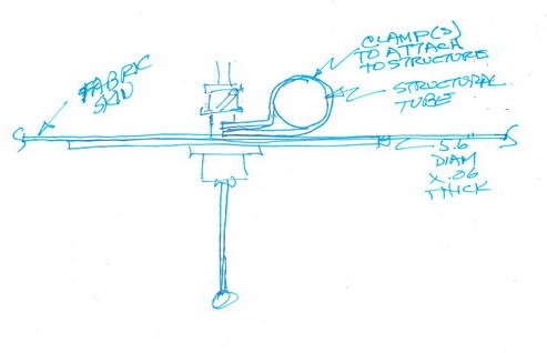
You said tube structure . . . fabric or metal skin?


 If fabric, a 5.6" alum disk .060 or so thick

 is an appropriate ground plane.


 [img]cid:.0[/img]

 If your fabric is 'tight' against a structural

 tube, then the ground plane can go on the outside

 surface. It would look cleaner if between skin

 and tube.  One or more clamps should secure the

 ground plane to structure . . . not for electrical

 'bonding' but for mechanical support.

 [img]cid:.1[/img]


 Whether the ground is inside or outside the

 skin, the antenna should mount in the center

 with good electrical connection between antenna

 base and the ground plane.


 If metal skin, simply mount antenna to skin

 but consider double of any practical size

 to re-enforce the mounting surface to preclude

 cracking around mounting hole due to aerodynamic

 buffeting.


 VHF comm antennas need good support to the

 ship's tubular structure. If metal airplane,

 ground antenna base to skin. If fabric covered

 airplane, ground a suitable mounting plate

 to the ship's structure then ground antenna

 to the mounting plate. Ship's structure

 becomes the ground plane.


   Bob . . .
| | - The Matronics AeroElectric-List Email Forum - | | | Use the List Feature Navigator to browse the many List utilities available such as the Email Subscriptions page, Archive Search & Download, 7-Day Browse, Chat, FAQ, Photoshare, and much more:
http://www.matronics.com/Navigator?AeroElectric-List |
|
| Description: |
|
| Filesize: |
49.7 KB |
| Viewed: |
20117 Time(s) |
|
| Description: |
|
| Filesize: |
6.02 KB |
| Viewed: |
20117 Time(s) |

|
|
|
| Back to top |
|
 |
Argonaut36
Joined: 19 May 2019
Posts: 35
|
| Posted: Mon Sep 16, 2019 7:36 pm Post subject: Re: Grounding radio antenna and transponder antenna |
|
|
Bob,

Thanks for your post and for the sketch.

Please note that my airplane has a standard certificate.  It is not experimental. The antenna is mounted on a removable panel on the bottom of the airplane; the antenna was installed professionally on the panel and I have not had any structural problems in many years of flying.  The panel is made of metal except for a plexigas window and doubles as the radio antenna ground plane, even if it is kind of small for that purpose.  I have installed some metal tape that goes over the plexigas trying to improve things.  The panel is attached to a vertical metal panel on each side with machine screws/anchor nuts.   At the front, the panel overlaps another metal panel and connects to a little beam with sheet metal screws.  At the back, the panel overlaps a fabric panel and connects to a little beam with sheet metal screws.

As mentioned above, this panel is removable and needs to come out of the airplane for maintenance purposes a few times a year.  It would be difficult to make modifications to this panel.  I have noticed that the transponder antenna ground plane is grounded to the plane tubular frame and I am just trying to establish if the radio antenna panel should also be grounded or not and why.

Thanks for your help.
| | - The Matronics AeroElectric-List Email Forum - | | | Use the List Feature Navigator to browse the many List utilities available such as the Email Subscriptions page, Archive Search & Download, 7-Day Browse, Chat, FAQ, Photoshare, and much more:
http://www.matronics.com/Navigator?AeroElectric-List |
|
|
|
| Back to top |
|
|
user9253
Joined: 28 Mar 2008
Posts: 1969
Location: Riley TWP Michigan
|
| Posted: Tue Sep 17, 2019 12:17 am Post subject: Re: Grounding radio antenna and transponder antenna |
|
|
Since this is a factory built aircraft, and assuming that several of this brand and model have been built without radio problems, then maybe the problem with your radio is not an antenna design problem.  Maybe there is a problem with the coax or its connection at either end.  Would it be difficult to replace the coax?

What are the dimensions of the metal panel used for the ground plane?  Have you removed the antenna and reinstalled it to be sure that there is a good electrical connection to the ground plane?  We are talking about a com radio antenna, right?
| | - The Matronics AeroElectric-List Email Forum - | | | Use the List Feature Navigator to browse the many List utilities available such as the Email Subscriptions page, Archive Search & Download, 7-Day Browse, Chat, FAQ, Photoshare, and much more:
http://www.matronics.com/Navigator?AeroElectric-List |
|
_________________
Joe Gores |
|
| Back to top |
|
|
Argonaut36
Joined: 19 May 2019
Posts: 35
|
| Posted: Tue Sep 17, 2019 7:24 am Post subject: Re: Grounding radio antenna and transponder antenna |
|
|
The airplane is a Pitts and Pitts are known for poor radio transmissions.

I know that I cannot get a perfect radio, I am just trying to improve on what I have got.


The coax was replaced with  a new one, made by a reputable avionics shop.  That made a difference.


The antenna (and yes, we are talking about a com antenna) was replaced with a new one and was installed on the panel by a competent technician, paying particular attention to getting a good electrical connection.


The dimensions of the ground plane are length 7"  x  width 14".  The 14" width is made up follow: central section: 6":,   side sections: 4" with an angle of 15-20 degrees in relation to the central section.
| | - The Matronics AeroElectric-List Email Forum - | | | Use the List Feature Navigator to browse the many List utilities available such as the Email Subscriptions page, Archive Search & Download, 7-Day Browse, Chat, FAQ, Photoshare, and much more:
http://www.matronics.com/Navigator?AeroElectric-List |
|
|
|
| Back to top |
|
|
nuckolls.bob(at)aeroelect
Guest
|
| Posted: Tue Sep 17, 2019 8:38 am Post subject: Grounding radio antenna and transponder antenna |
|
|
At 10:24 AM 9/17/2019, you wrote:
| Quote: | --> AeroElectric-List message posted by: "Argonaut36" <fmlibrino(at)msn.com>
The airplane is a Pitts and Pitts are known for poor radio transmissions.
I know that I cannot get a perfect radio, I am just trying to improve on what I have got. |
Do you still have the old coax?
I'd like to put my hands on it . . .
The antenna (and yes, we are talking about a com antenna) was replaced with a new one and was installed on the panel by a competent technician, paying particular attention to getting a good electrical connection.
Hmmm . . . vhf comm is line-of-sight
bounded with very low path losses.
Except for 'shielding' effects of surrounding
structure, satisfactory communications can
be expected with rather low power and
less-than-perfect antennas.
The dimensions of the ground plane are length 7" x width 14". The 14" width is made up follows: central section: 6":, side sections: 4" with an angle of 15-20 degrees in relation to the central section.
. . . but attached to metal airframe
components at various places around
the edges? While not an 'ideal'
ground plane it should certainly
be adequate for all but the occasional
extreme range situation while x-country.
I am just trying to establish if the radio antenna panel should also be grounded or not and why.
If there are numerous fasteners connecting
the removable panel to metallic components
of the airframe, it's unlikely that
any additional 'grounding' will produce
observable improvement.
You have a new antenna and coax . . . are
you still experiencing unsatisfactory
performance? Have you ever had occasion
to use a hand-held radio in this
airplane?
Sorry for the run-off into the weeds.
Bob . . .
| | - The Matronics AeroElectric-List Email Forum - | | | Use the List Feature Navigator to browse the many List utilities available such as the Email Subscriptions page, Archive Search & Download, 7-Day Browse, Chat, FAQ, Photoshare, and much more:
http://www.matronics.com/Navigator?AeroElectric-List |
|
|
|
| Back to top |
|
|
user9253
Joined: 28 Mar 2008
Posts: 1969
Location: Riley TWP Michigan
|
| Posted: Tue Sep 17, 2019 10:06 am Post subject: Re: Grounding radio antenna and transponder antenna |
|
|
7 x 14 inches is way too small for a ground plane if it is not attached to the airframe on all 4 sides. So make your own ground plane. Here is a quote from chapter 13 of Bob's book:
"VHF ground-planes can be fabricated from radial strips of copper foil, soldered to a communing disk at the base of the antenna. Make these strips 1â wide and trim them off 22â from the base of the vertical. 4 to 10 strips are recommended. These may be cemented to the underside of the skin and structure. By fabricating a commoning disk from copper, the entire assembly can be soldered."
| | - The Matronics AeroElectric-List Email Forum - | | | Use the List Feature Navigator to browse the many List utilities available such as the Email Subscriptions page, Archive Search & Download, 7-Day Browse, Chat, FAQ, Photoshare, and much more:
http://www.matronics.com/Navigator?AeroElectric-List |
|
_________________
Joe Gores |
|
| Back to top |
|
|
nuckolls.bob(at)aeroelect
Guest
|
| Posted: Tue Sep 17, 2019 1:17 pm Post subject: Grounding radio antenna and transponder antenna |
|
|
At 01:06 PM 9/17/2019, you wrote:
| Quote: | --> AeroElectric-List message posted by: "user9253" <fransew(at)gmail.com>
7 x 14 inches is way too small for a ground plane if it is not attached to the airframe on all 4 sides. |
While a long way from the idealized ground
plane, it's not insignificant. After all,
how much ground plane does a hand-held
transceiver have?
We're told that these aircraft have a
history of poor radio performance . . .
but they've been built in various types
and quantities for over 50 years. Given
that this is a t/c aircraft, I'm inclined
believe that the problem(s) with this
airplane may be more selective than a
poorly designed antenna installation.
We're advised that replacing the coax
made an improvement . . . and that
the antenna has been replaced with
extra attention to process. We're
not sure yet if this fixed things.
Bob . . .
| | - The Matronics AeroElectric-List Email Forum - | | | Use the List Feature Navigator to browse the many List utilities available such as the Email Subscriptions page, Archive Search & Download, 7-Day Browse, Chat, FAQ, Photoshare, and much more:
http://www.matronics.com/Navigator?AeroElectric-List |
|
|
|
| Back to top |
|
|
nuckolls.bob(at)aeroelect
Guest
|
| Posted: Tue Sep 17, 2019 1:26 pm Post subject: Grounding radio antenna and transponder antenna |
|
|
At 01:06 PM 9/17/2019, you wrote:
| Quote: | --> AeroElectric-List message posted by: "user9253" <fransew(at)gmail.com>
7 x 14 inches is way too small for a ground plane if it is not attached to the airframe on all 4 sides. |
While a long way from the idealized ground
plane, it's not insignificant. After all,
how much ground plane area does a hand-held
transceiver have?
We're told that these aircraft have a
history of poor radio performance . . .
but they've been built in various types
and quantities for over 50 years. Given
that this is a t/c aircraft, I'm inclined
to think that the problem(s) with this
airplane may be more selective than a
poorly designed antenna installation.
We're advised that replacing the coax
made an improvement . . . and that
the antenna has been replaced with
extra attention to process. We're
not sure yet if this fixed things.
Given the ease with which VHF communication
propagates between aviation facilities,
I'm inclined to believe that root cause
for unsatisfactory performance is more
profound than a soggy ground plane.
In the words of the immortal, slightly
short-circuited Number 5, "Input! Input!
I need more input!"
Bob . . .
| | - The Matronics AeroElectric-List Email Forum - | | | Use the List Feature Navigator to browse the many List utilities available such as the Email Subscriptions page, Archive Search & Download, 7-Day Browse, Chat, FAQ, Photoshare, and much more:
http://www.matronics.com/Navigator?AeroElectric-List |
|
|
|
| Back to top |
|
|
Argonaut36
Joined: 19 May 2019
Posts: 35
|
| Posted: Tue Sep 17, 2019 6:39 pm Post subject: Re: Grounding radio antenna and transponder antenna |
|
|
Thanks to both for the additional comments.
I reply to the questions of Bob as follows:
⢠I do not have the old coax any more
⢠I have never used a hand-held radio in this airplane
⢠The radio performance is ok for Class D operations, but not so good for Class B and Class C, when you need to communicate from further out and clarity of communications is even more important
⢠As far as additional input, I can tell you that the radio harness was replaced without appreciable changes
I am posting a file that includes 2 pictures of my panel/antenna. The copper strips are just taped (not soldered) and there is no communing disk. The strips do not extend laterally, because of the limited width of the panel. I assumed that, as we normally fly towards the radio station we are talking to, that would be kind of acceptable.
Could you please make comments on my copper foil strips and elaborate a little further on how the set up described by Bob is in his book could be implemented on my panel (keeping the panel removable from the airplane)?
Note: in my previous post with the dimensions of the ground plane I have just disregarded the copper foil strips and I have assumed that the section of panel behind the plexigas window and the double plate work together as a ground plane.
Thanks
| | - The Matronics AeroElectric-List Email Forum - | | | Use the List Feature Navigator to browse the many List utilities available such as the Email Subscriptions page, Archive Search & Download, 7-Day Browse, Chat, FAQ, Photoshare, and much more:
http://www.matronics.com/Navigator?AeroElectric-List |
|
| Description: |
|

Download |
| Filename: |
Pictures.pdf |
| Filesize: |
542.39 KB |
| Downloaded: |
688 Time(s) |
|
|
| Back to top |
|
|
user9253
Joined: 28 Mar 2008
Posts: 1969
Location: Riley TWP Michigan
|
| Posted: Wed Sep 18, 2019 7:25 am Post subject: Re: Grounding radio antenna and transponder antenna |
|
|
That copper tape does not do much good because it all goes in one direction.  And it is questionable if it is making good contact with the antenna mounting plate.

Here is a suggestion: Cut 4 pieces of coax each 24 inches long.  Attach a ring terminal to the shield of each coax (not the center conductor).  Connect one length of coax to each of the 4 antenna mounting screws using the ring terminals.  When the panel is mounted to the aircraft, arrange the coax ground plane so that it extends outward in 4 different directions.  Elastic cord attached to the coax ends could help to position it.

This experiment is worth a try and will not cost much except your time.
| | - The Matronics AeroElectric-List Email Forum - | | | Use the List Feature Navigator to browse the many List utilities available such as the Email Subscriptions page, Archive Search & Download, 7-Day Browse, Chat, FAQ, Photoshare, and much more:
http://www.matronics.com/Navigator?AeroElectric-List |
|
_________________
Joe Gores
Last edited by user9253 on Thu Sep 19, 2019 5:33 am; edited 1 time in total |
|
| Back to top |
|
|
nuckolls.bob(at)aeroelect
Guest
|
| Posted: Wed Sep 18, 2019 12:09 pm Post subject: Grounding radio antenna and transponder antenna |
|
|
At 10:57 PM 9/17/2019, you wrote:
| Quote: | If the copper tape isn't soldered or otherwise electrically bonded to the rest of the metal ground plane (panel), then it's not doing anything productive. You could get what you were hoping for by using strips of aluminum; even something really thin like strips cut from aluminum flashing material. They could be riveted on one end to the aluminum doubler shown in the pics, and glued with clear 'sensor safe' rtv to the plexi, and screwed at the other end using the plexi mounting screws.Â
Having said that, the antenna still won't be centered in the ground plane. You could add strips going the other direction using similar techniques. The 'ideal' ground plane extends out from the base as far as the antenna height. As few as 4 equally spaced radial arms can get the job done pretty effectively. |
Actually, there's a relatively simple experiment
that can be conducted. 4 radials ~1" wide, extending
from the antenna base and simply taped to the outside
surface of the a/c will emulate an excellent ground
plane. It does not need to be electrically bonded to
the airframe. Where it is in close proximity to the
airframe, there will be significant electro-static
coupling to the airframe. I'd make them 24" long or
so. Length not critical when so closely coupled to
the a/c skin. Here's a tape suited to the task of
temporary attachment to the airplane.
https://tinyurl.com/y3wrc7kx
I've used this stuff to run ribbon cable through
the baggage door seal, down the side of the fuselage
and past the entry door seal to bring investigatory
signals from the hell-hole of a Beechjet into the
cabin.
This tape would work fine for the experimental ground
plane installation as well.
| Quote: |
Having said *that*, are you sure your problems are purely transmission range? Tube/rag a/c are notoriously noisy in the cockpit. You may have as much a problem with *audio* signal to noise ratio as with transmission distance. Ability to accurately describe comm deficiencies is pretty rare, even for controllers. If you think that could be a possibility, we can expand on that. |
Excellent point! There was a list-thread on
this very topic way back when . Turns out
that transmission intelligibility was
completely dependent on the noise cancelling
quality of microphone . . . I'm embarrassed
for not to have recalled this.
Before hammering on the antenna installation,
do try another mic/headset combination. They
are not all the same . . . particularly
with respect to cancelling low frequency
'buffeting' kinds of noise common to airplanes
where creature comfort is rather far down on the
list of design priorities.
Is it just your transmitted signal that's
deficient . . . or both transmit and receive?
This brings up the point that few users
of two-way radios have the experience and vocabulary
to describe poor signal quality. For example,
you can have a strong radio frequency signal
that is dead quiet when not talking but the
audio is weak/distorted. This is ALWAYS an
audio/microphone problem. You can have
a marginal radio frequency signal (just
beginning to present 'popcorn' noises
when not talking and uncharacteristically
poor audio when adding voice modulation.
Then there's the truly weak-signal which
can be a combination of radio/coax/antenna
issued. Years ago, I asked a reader to
send me a recording of his received signal
as heard on the ground . . . his problem
turned out to be in the audio system causing
a badly under-modulated transmitter.
Charlie's memory jog suggests an
important avenue of investigation
that supercedes fiddling with the antenna.
Bob . . .
| | - The Matronics AeroElectric-List Email Forum - | | | Use the List Feature Navigator to browse the many List utilities available such as the Email Subscriptions page, Archive Search & Download, 7-Day Browse, Chat, FAQ, Photoshare, and much more:
http://www.matronics.com/Navigator?AeroElectric-List |
|
|
|
| Back to top |
|
|
nuckolls.bob(at)aeroelect
Guest
|
| Posted: Wed Sep 18, 2019 12:09 pm Post subject: Grounding radio antenna and transponder antenna |
|
|
At 10:25 AM 9/18/2019, you wrote:
| Quote: | --> AeroElectric-List message posted by: "user9253" <fransew(at)gmail.com>
That copper tape does not do much good because it all goes in one direction. And it is questionable if it is making good contact with the antenna mounting plate.
Here is a suggestion: Cut 4 pieces of coax each 22 or 23 inches long. Attach a ring terminal to the shield of each coax (not the center conductor). Connect one length of coax to each of the 4 antenna mounting screws using the ring terminals. When the panel is mounted to the aircraft, arrange the coax ground plane so that it extends outward in 4 different directions. Elastic cord attached to the coax ends could help to position it.
This experiment is worth a try and will not cost much except your time. |
That would work too . . . the same tape could
be used to hold it against the skin.
Bob . . .
| | - The Matronics AeroElectric-List Email Forum - | | | Use the List Feature Navigator to browse the many List utilities available such as the Email Subscriptions page, Archive Search & Download, 7-Day Browse, Chat, FAQ, Photoshare, and much more:
http://www.matronics.com/Navigator?AeroElectric-List |
|
|
|
| Back to top |
|
|
nuckolls.bob(at)aeroelect
Guest
|
| Posted: Thu Sep 19, 2019 4:55 am Post subject: Grounding radio antenna and transponder antenna |
|
|
At 10:57 PM 9/17/2019, you wrote:
| Quote: | If the copper tape isn't soldered or otherwise electrically bonded to the rest of the metal ground plane (panel), then it's not doing anything productive. You could get what you were hoping for by using strips of aluminum; even something really thin like strips cut from aluminum flashing material. They could be riveted on one end to the aluminum doubler shown in the pics, and glued with clear 'sensor safe' rtv to the plexi, and screwed at the other end using the plexi mounting screws.Â
Having said that, the antenna still won't be centered in the ground plane. You could add strips going the other direction using similar techniques. The 'ideal' ground plane extends out from the base as far as the antenna height. As few as 4 equally spaced radial arms can get the job done pretty effectively. |
Actually, there's a relatively simple experiment
that can be conducted. 4 radials ~1" wide, extending
from the antenna base and simply taped to the outside
surface of the a/c will emulate an excellent ground
plane. It does not need to be electrically bonded to
the airframe. Where it is in close proximity to the
airframe, there will be significant electro-static
coupling to the airframe. I'd make them 24" long or
so. Length not critical when so closely coupled to
the a/c skin. Here's a tape suited to the task of
temporary attachment to the airplane.
https://tinyurl.com/y3wrc7kx
I've used this stuff to run ribbon cable through
the baggage door seal, down the side of the fuselage
and past the entry door seal to bring investigatory
signals from the hell-hole of a Beechjet into the
cabin.
This tape would work fine for the experimental ground
plane installation as well.
| Quote: |
Having said *that*, are you sure your problems are purely transmission range? Tube/rag a/c are notoriously noisy in the cockpit. You may have as much a problem with *audio* signal to noise ratio as with transmission distance. Ability to accurately describe comm deficiencies is pretty rare, even for controllers. If you think that could be a possibility, we can expand on that. |
Excellent point! There was a list-thread on
this very topic way back when . Turns out
that transmission intelligibility was
completely dependent on the noise cancelling
quality of microphone . . . I'm embarrassed
for not to have recalled this.
Before hammering on the antenna installation,
do try another mic/headset combination. They
are not all the same . . . particularly
with respect to cancelling low frequency
'buffeting' kinds of noise common to airplanes
where creature comfort is rather far down on the
list of design priorities.
Is it just your transmitted signal that's
deficient . . . or both transmit and receive?
This brings up the point that few users
of two-way radios have the experience and vocabulary
to describe poor signal quality. For example,
you can have a strong radio frequency signal
that is dead quiet when not talking but the
audio is weak/distorted. This is ALWAYS an
audio/microphone problem. You can have
a marginal radio frequency signal (just
beginning to present 'popcorn' noises
when not talking and uncharacteristically
poor audio when adding voice modulation.
Then there's the truly weak-signal which
can be a combination of radio/coax/antenna
issued. Years ago, I asked a reader to
send me a recording of his received signal
as heard on the ground . . . his problem
turned out to be in the audio system causing
a badly under-modulated transmitter.
Charlie's memory jog suggests an
important avenue of investigation
that supercedes fiddling with the antenna.
Bob . . .
| | - The Matronics AeroElectric-List Email Forum - | | | Use the List Feature Navigator to browse the many List utilities available such as the Email Subscriptions page, Archive Search & Download, 7-Day Browse, Chat, FAQ, Photoshare, and much more:
http://www.matronics.com/Navigator?AeroElectric-List |
|
|
|
| Back to top |
|
|
nuckolls.bob(at)aeroelect
Guest
|
| Posted: Thu Sep 19, 2019 4:56 am Post subject: Grounding radio antenna and transponder antenna |
|
|
At 10:25 AM 9/18/2019, you wrote:
| Quote: | --> AeroElectric-List message posted by: "user9253" <fransew(at)gmail.com>
That copper tape does not do much good because it all goes in one direction. And it is questionable if it is making good contact with the antenna mounting plate.
Here is a suggestion: Cut 4 pieces of coax each 22 or 23 inches long. Attach a ring terminal to the shield of each coax (not the center conductor). Connect one length of coax to each of the 4 antenna mounting screws using the ring terminals. When the panel is mounted to the aircraft, arrange the coax ground plane so that it extends outward in 4 different directions. Elastic cord attached to the coax ends could help to position it.
This experiment is worth a try and will not cost much except your time. |
That would work too . . . the same tape could
be used to hold it against the skin.
Bob . . .
| | - The Matronics AeroElectric-List Email Forum - | | | Use the List Feature Navigator to browse the many List utilities available such as the Email Subscriptions page, Archive Search & Download, 7-Day Browse, Chat, FAQ, Photoshare, and much more:
http://www.matronics.com/Navigator?AeroElectric-List |
|
|
|
| Back to top |
|
|
user9253
Joined: 28 Mar 2008
Posts: 1969
Location: Riley TWP Michigan
|
| Posted: Thu Sep 19, 2019 5:37 am Post subject: Re: Grounding radio antenna and transponder antenna |
|
|
I changed the length of the ground plane radials to 24 inches in my post above to be the same as Bob's suggestion.
| | - The Matronics AeroElectric-List Email Forum - | | | Use the List Feature Navigator to browse the many List utilities available such as the Email Subscriptions page, Archive Search & Download, 7-Day Browse, Chat, FAQ, Photoshare, and much more:
http://www.matronics.com/Navigator?AeroElectric-List |
|
_________________
Joe Gores |
|
| Back to top |
|
|
nuckolls.bob(at)aeroelect
Guest
|
| Posted: Thu Sep 19, 2019 7:27 am Post subject: Grounding radio antenna and transponder antenna |
|
|
At 08:37 AM 9/19/2019, you wrote:
| Quote: | --> AeroElectric-List message posted by: "user9253" <fransew(at)gmail.com>
I changed the length of the ground plane radials to 24 inches in my post above to be the same as Bob's suggestion. |
The length won't be 'critical' in this case.
When crafting a free space ground plane for
a vertical antenna, the idea is to approximate
the 'perfect' ground plane . . . a solid conductor
radiating from the base of the antenna for a
long ways. Since an perfect (infinite)
plane isn't practical, the common approximations
take on the form of radial 'whiskers'
[img]https://www.bing.com/th?id=OIP.frzhTHSL4nWMxO4KqsPwpAHaDU&w=300&h=134&c=7&o=5&dpr=1.25&pid=1.7[/img]
In this case, they are just more antennas
brought together at the base such that their
impedances are paralleled. The more radials,
the lower the ground impedance, the better
the plane. These are resonant ground planes.
I.e. 1/4 wave in free space elements.
This technique is closely approximated
in composite airplanes with copper or
aluminum strips bonded to the inside
skin of the aircraft.
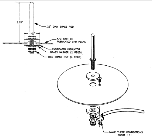
The DIY transponder antenna for composite
applications suggeseted a solid disk
ground plane with a radius equal to height
of the antenna.
[img]cid:.0[/img]
This 'plane' looks like an infinite number
of radials joined at the center. But
unless the plane is in pretty much free
space with respect to surrounding conductors,
it's near-ideal characteristics are
degraded.
For the purposed of our 'experiment',
the proposed 1/4 wave elements will be in
closest practical proximity to a metal
airframe; no longer in free air and
certainly not resonant at the frequency
of interest.
So the exact length is no longer significant.
Instead we're looking for some electro-static
or capacitive coupling to the airframe to
combine with planar effects of the now-random
lengths of conductor. In this case, the
wider strips taped to the skin are more
desirable to increase the capacitive coupling
effects . . . but the suggested wire elements
may well produce the desired effect of compensating
for a suspected inadequate ground plane.
While the microphone performance issue is
worth examination, one of the 'grains of
sand' in this study says that performance
is degraded with DISTANCE from the other
station which discounts audio problems
(consistent irrespective of range) and
re-enforces the notion that there is a
signal strength issue.
Bob . . .
| | - The Matronics AeroElectric-List Email Forum - | | | Use the List Feature Navigator to browse the many List utilities available such as the Email Subscriptions page, Archive Search & Download, 7-Day Browse, Chat, FAQ, Photoshare, and much more:
http://www.matronics.com/Navigator?AeroElectric-List |
|
| Description: |
|
| Filesize: |
53.08 KB |
| Viewed: |
19977 Time(s) |
|
|
|
| Back to top |
|
|
Argonaut36
Joined: 19 May 2019
Posts: 35
|
| Posted: Thu Sep 19, 2019 5:50 pm Post subject: Re: Grounding radio antenna and transponder antenna |
|
|
Reference is made to the following comment of Bob in a recent post:
Quote
Years ago, I asked a reader to send me a recording of his received signal as heard on the ground . . . his problem turned out to be in the audio system causing a badly under-modulated transmitter.
Unquote
When the radio was almost new, it failed and I flew for a while with a loaned radio (identical) and then I got the replacement radio (also identical) that I have now. The three radios worked exactly the same and for this reason I did not consider the radio itself being the source of the troubles. At the time I flew with the other radios, however, I had different antenna, coax and harness that could have masked issues with the radio.
Going back to the alternative antenna configurations that have been proposed, could Bob please answer the following questions:
What is the recommended 1â copper foil tape and where I can buy it?
How is the tape terminated at the antenna? Does it stop at a certain distance from the antenna or right at the antenna?
Does the recommended 2" white vinyl tape leave adhesive residue on the paint? Considering that testing will probably require only a single short flight, could perhaps a less strong tape that does not leave residue be used?
Thanks
| | - The Matronics AeroElectric-List Email Forum - | | | Use the List Feature Navigator to browse the many List utilities available such as the Email Subscriptions page, Archive Search & Download, 7-Day Browse, Chat, FAQ, Photoshare, and much more:
http://www.matronics.com/Navigator?AeroElectric-List |
|
|
|
| Back to top |
|
|
user9253
Joined: 28 Mar 2008
Posts: 1969
Location: Riley TWP Michigan
|
|
| Back to top |
|
|
Argonaut36
Joined: 19 May 2019
Posts: 35
|
| Posted: Fri Sep 20, 2019 1:34 pm Post subject: Re: Grounding radio antenna and transponder antenna |
|
|
Thanks for the links for the copper foil tape and the installation suggestions.  I am not too sure about how easy would be to remove my existing antenna.  I remember that an adhesive that would provide a very strong bond between the antenna and the panel was used during  installation.

The other antenna option that uses the coax cable that was discussed in this thread seems easier and I plan on testing it the next time I have the panel out of the airplane.
| | - The Matronics AeroElectric-List Email Forum - | | | Use the List Feature Navigator to browse the many List utilities available such as the Email Subscriptions page, Archive Search & Download, 7-Day Browse, Chat, FAQ, Photoshare, and much more:
http://www.matronics.com/Navigator?AeroElectric-List |
|
|
|
| Back to top |
|
|
|
|
You cannot post new topics in this forum
You cannot reply to topics in this forum
You cannot edit your posts in this forum
You cannot delete your posts in this forum
You cannot vote in polls in this forum
You cannot attach files in this forum
You can download files in this forum
|
Powered by phpBB © 2001, 2005 phpBB Group
|

