 |
Matronics Email Lists
Web Forum Interface to the Matronics Email Lists
|
| View previous topic :: View next topic |
| Author |
Message |
Mudfly
Joined: 04 Feb 2012
Posts: 39
|
 Posted: Thu Feb 02, 2023 7:09 am Post subject: Primary Power Diagram RV-14 Posted: Thu Feb 02, 2023 7:09 am Post subject: Primary Power Diagram RV-14 |
 |
|
After many hours of reviewing diagrams from The AeroElectric Connection, I have arrived at the following "Initial Concept" for my RV14A project.

I am not experienced in airplane electrical design so any help with poor

design or possible safety concerns is appreciated.

Basic design features and goals:


*B&C Pri alternator will connect to battery contactor output side.


*B&C Stby alternator will connect to battery contactor input side.

  In the event of Pri Alt failure, and after a minute of thought, the three

 position (On-Off-On) ALT switch will be placed to the STBY ALT position.   If amp loading is within stby alt capabilities, flight will continue if no secondary issues are observed.   If load shed reqd, three position (On-Off-On) BATT/ESNTL switch will be placed to ESNTL position and, if dark stormy

night, flight will Land as Soon as Practical.   IF, I'm having a bad day and, for whatever reason (dual alt failure, electrical smoke/fire, etc), I need to shut

off battery and alternators, the two TCW IBBS batts should pick up essential systems and I will Land as Soon as Possible.  IF, I'm having a really bad day and smoke/fire /fumes continue, I will secure battery, alternators,

STBY Bats, and get down as best I can using the AV-30 stand-by flight

display.


*Hot Battery Bus -This bus is hot anytime battery is connected. It is located

in the avionics sub-panel which is which is easily accessible on pre-flight,

but not during flight. Initially for a couple items, but more added because I

ran

 out of space on main CB panel. All but one item on this bus is switched.


*Two TCW-IBBS-12v-6ah batteries. One provides b/u power for PFD1 and associated items. The second is for the GTN650Xi. Because the GTN650

does not have pins for a b/u power source, I moved it to its own bus.

If needed,

 that bus will be powered by its own b/u batt.


*Ignitions - One Surefly and one slick Mag.

After typing that all out, it sounds pretty "busy".  I realize not as simple a

 setup as some prefer, but hopefully it's not excessive.   Again, I'm open to

 all critiques and suggestions especially related to bad design and safety of

flight.

Thanks for your input.

Shawn Edwards
| | - The Matronics AeroElectric-List Email Forum - | | | Use the List Feature Navigator to browse the many List utilities available such as the Email Subscriptions page, Archive Search & Download, 7-Day Browse, Chat, FAQ, Photoshare, and much more:
http://www.matronics.com/Navigator?AeroElectric-List |
|
| Description: |
|

Download |
| Filename: |
N144EF.pdf |
| Filesize: |
202.65 KB |
| Downloaded: |
653 Time(s) |
Last edited by Mudfly on Sun Feb 19, 2023 5:02 pm; edited 3 times in total |
|
| Back to top |
|
 |
Ceengland
Joined: 11 Oct 2020
Posts: 398
Location: MS
|
| Posted: Thu Feb 02, 2023 7:47 am Post subject: Primary Power Diagram RV-14 |
|
|
On 2/2/2023 9:09 AM, Mudfly wrote:
| Quote: |
After many hours of reviewing diagrams from The AeroElectric Connection, I have arrived at the following "Initial Concept" for my RV14A project.
I am not experienced in airplane electrical design so any help with poor design or possible safety concerns is appreciated.
Basic design features and goals:
*B&C Pri alternator will connect to battery contactor output side.
*B&C Stby alternator will connect to battery contactor input side.
In the event of Pri Alt failure, and after a minute of thought, the three position (On-Off-On) ALT switch will be placed to the STBY ALT position. If amp loading is within stby alt capabilities, flight will continue if no secondary issues are observed. If load shed reqd, three position (On-Off-On) BATT/ESNTL switch will be placed to ESNTL position and, if dark stormy night, flight will Land as Soon as Practical. IF, I'm having a bad day and, for whatever reason (dual alt failure, electrical smoke/fire, etc), I need to shut off battery and alternators, the two TCW IBBS batts should pick up essential systems and I will Land as Soon as Possible. IF, I'm having a really bad day and smoke/fire /fumes continue, I will secure battery, alternators, STBY Bats, and get down as best I can using the AV-30 stand-by flight display.
*Hot Battery Bus -This bus is hot anytime battery is connected. It is located in the avionics sub-panel which is which is easily accessible on pre-flight, but not during flight. Initially for a couple items, but more added because I ran out of space on main CB panel. All but one item on this bus is switched.
*Two TCW-IBBS-12v-6ah batteries. One provides b/u power for PFD1 and associated items. The second is for the GTN650Xi. Because the GTN650 does not have pins for a b/u power source, I moved it to its own bus. If needed, that bus will be powered by its own b/u batt.
*Ignitions - One Surefly and one slick Mag.
After typing that all out, it sounds pretty "busy". I realize not as simple a setup as some prefer, but hopefully it's not excessive. Again, I'm open to all critiques and suggestions especially related to bad design and safety of flight.
Thanks for your input.
Shawn Edwards
Hi Shawn,
|
I hit pause at, 'the three position (On-Off-On) ALT switch will be
placed to the STBY ALT position.'
That becomes a single point of failure; if the switch fails
mechanically, you could lose both alternators.
Also, if I understand the design of the B&C regulators, no switch should
be unneeded. The standby regulator should keep the standby alt offline
unless the main has failed, and automatically bring the standby online
if that happens.
FWIW,
Charlie
--
This email has been checked for viruses by Avast antivirus software.
www.avast.com
| | - The Matronics AeroElectric-List Email Forum - | | | Use the List Feature Navigator to browse the many List utilities available such as the Email Subscriptions page, Archive Search & Download, 7-Day Browse, Chat, FAQ, Photoshare, and much more:
http://www.matronics.com/Navigator?AeroElectric-List |
|
_________________
Charlie |
|
| Back to top |
|
|
david(at)carter.net
Guest
|
| Posted: Thu Feb 02, 2023 9:17 am Post subject: Primary Power Diagram RV-14 |
|
|
I suggest comparing your design to this, which is Bob's latest state-of-the-art:
http://www.aeroelectric.com/PPS/Adobe_Architecture_Pdfs/Z101B.pdf
---
David Carter
david(at)carter.net (david(at)carter.net)
On Thu, Feb 2, 2023 at 10:48 AM Charlie England <ceengland7(at)gmail.com (ceengland7(at)gmail.com)> wrote:
| Quote: | --> AeroElectric-List message posted by: Charlie England <ceengland7(at)gmail.com (ceengland7(at)gmail.com)>
On 2/2/2023 9:09 AM, Mudfly wrote:
> --> AeroElectric-List message posted by: "Mudfly" <shawntedwards(at)hotmail.com (shawntedwards(at)hotmail.com)>
>
> After many hours of reviewing diagrams from The AeroElectric Connection, I have arrived at the following "Initial Concept" for my RV14A project.
> I am not experienced in airplane electrical design so any help with poor design or possible safety concerns is appreciated.
> Basic design features and goals:
>
> *B&C Pri alternator will connect to battery contactor output side.
>
> *B&C Stby alternator will connect to battery contactor input side.
> In the event of Pri Alt failure, and after a minute of thought, the three position (On-Off-On) ALT switch will be placed to the STBY ALT position. If amp loading is within stby alt capabilities, flight will continue if no secondary issues are observed. If load shed reqd, three position (On-Off-On) BATT/ESNTL switch will be placed to ESNTL position and, if dark stormy night, flight will Land as Soon as Practical. IF, I'm having a bad day and, for whatever reason (dual alt failure, electrical smoke/fire, etc), I need to shut off battery and alternators, the two TCW IBBS batts should pick up essential systems and I will Land as Soon as Possible. IF, I'm having a really bad day and smoke/fire /fumes continue, I will secure battery, alternators, STBY Bats, and get down as best I can using the AV-30 stand-by flight display.
>
> *Hot Battery Bus -This bus is hot anytime battery is connected. It is located in the avionics sub-panel which is which is easily accessible on pre-flight, but not during flight. Initially for a couple items, but more added because I ran out of space on main CB panel. All but one item on this bus is switched.
>
> *Two TCW-IBBS-12v-6ah batteries. One provides b/u power for PFD1 and associated items. The second is for the GTN650Xi. Because the GTN650 does not have pins for a b/u power source, I moved it to its own bus. If needed, that bus will be powered by its own b/u batt.
>
> *Ignitions - One Surefly and one slick Mag.
>
> After typing that all out, it sounds pretty "busy". I realize not as simple a setup as some prefer, but hopefully it's not excessive. Again, I'm open to all critiques and suggestions especially related to bad design and safety of flight.
> Thanks for your input.
> Shawn Edwards
Hi Shawn,
I hit pause at, 'the three position (On-Off-On) ALT switch will be
placed to the STBY ALT position.'
That becomes a single point of failure; if the switch fails
mechanically, you could lose both alternators.
Also, if I understand the design of the B&C regulators, no switch should
be unneeded. The standby regulator should keep the standby alt offline
unless the main has failed, and automatically bring the standby online
if that happens.
FWIW,
Charlie
--
This email has been checked for viruses by Avast antivirus software.
www.avast.com
===========
-
Electric-List" rel="noreferrer" target="_blank">http://www.matronics.com/Navigator?AeroElectric-List
===========
FORUMS -
eferrer" target="_blank">http://forums.matronics.com
===========
WIKI -
errer" target="_blank">http://wiki.matronics.com
===========
b Site -
-Matt Dralle, List Admin.
="noreferrer" target="_blank">https://matronics.com/contribution
===========
|
| | - The Matronics AeroElectric-List Email Forum - | | | Use the List Feature Navigator to browse the many List utilities available such as the Email Subscriptions page, Archive Search & Download, 7-Day Browse, Chat, FAQ, Photoshare, and much more:
http://www.matronics.com/Navigator?AeroElectric-List |
|
|
|
| Back to top |
|
|
Mudfly
Joined: 04 Feb 2012
Posts: 39
|
| Posted: Thu Feb 02, 2023 6:05 pm Post subject: Re: Primary Power Diagram RV-14 |
|
|
Thanks Charlie.  I'm glad you made it all the way to my Alt switch before

 hitting pause.  So you're saying there's a chance:)  You're points are valid

and I appreciate the feedback.  However, while I don't have primary power wires in place yet, I do have my panel cut and labeled.  Looking back, I may have put the cart before the horse here.   So,.. if possible,  I will try and

stick to my switch configurations, where I can,  as long as it allows for an overall safe/acceptable risk design.   In the case of my Alt switching setup,

 I may accept this single point of failure (I'll add it to the long list of others

I've encountered during the project), and develop procedures and checklists

to utilize the back-up equipment I have onboard to mitigate risk when

failures do occur.

Shawn


I hit pause at, 'the three position (On-Off-On) ALT switch will be

placed to the STBY ALT position.'

That  becomes a single point of failure; if the switch fails

mechanically, you could lose both alternators.

Also, if I understand the design of the B&C regulators, no switch should

be unneeded. The standby regulator should keep the standby alt offline

unless the main has failed, and automatically bring the standby online

if that happens.


FWIW,


Charlie


--

This email has been checked for viruses by Avast antivirus software.

www.avast.com[/quote]
| | - The Matronics AeroElectric-List Email Forum - | | | Use the List Feature Navigator to browse the many List utilities available such as the Email Subscriptions page, Archive Search & Download, 7-Day Browse, Chat, FAQ, Photoshare, and much more:
http://www.matronics.com/Navigator?AeroElectric-List |
|
Last edited by Mudfly on Sun Feb 19, 2023 5:03 pm; edited 4 times in total |
|
| Back to top |
|
|
Mudfly
Joined: 04 Feb 2012
Posts: 39
|
| Posted: Sun Feb 05, 2023 5:36 am Post subject: Re: Primary Power Diagram RV-14 |
|
|
Small changes to the Primary Power System diagram.

Also added interconnect drawing for STBY Batteries.

Updated drawings attached.(UPDATE 2/7/22 -REMOVED INTERCONNECT DRAWING FOR STBY BATTERIES -- AFTER CONSULTING TCW, I WAS ADVISED MY DIAGRAM WAS WIRED INCORRECTLY)  Back to the drawing board for that system.
| | - The Matronics AeroElectric-List Email Forum - | | | Use the List Feature Navigator to browse the many List utilities available such as the Email Subscriptions page, Archive Search & Download, 7-Day Browse, Chat, FAQ, Photoshare, and much more:
http://www.matronics.com/Navigator?AeroElectric-List |
|
| Description: |
|
Download |
| Filename: |
Primary Power System.pdf |
| Filesize: |
202.59 KB |
| Downloaded: |
653 Time(s) |
|
|
| Back to top |
|
|
johnbright
Joined: 14 Dec 2011
Posts: 166
Location: Newport News, VA
|
| Posted: Thu Feb 09, 2023 3:47 pm Post subject: Re: Primary Power Diagram RV-14 |
|
|
Re "Primary Power System.pdf" RV-14A N144EF rev in work 02/04/2023


I have a number of suggestions that I can peck away at. I’ll start with the battery bus to make it meet FAR 23.1361:


Mount it on the forward side of the firewall.

Connect it straight to the battery with no current limiter or fuse. No protection required and each joint between the battery and the battery bus is a potential failure point.

Short feeder length, say 6" or less fashioned with best practices to make a short to ground practically impossible.

10 awg hookup wire is fine but 12 or 14 would be fine also. These are conventionally rated for 30, 20, and 15 A respectively.

Keep all the fuses 7-1/2A or less.

This will meet the spirit of FAR 23.1361 which is important for service and crash safety scenarios. Why 7-1/2A fuses instead of the 5A or less "protective device" specified in FAR 23.1361?... because as Bob Nuckolls points out, fuses are much faster than circuit breakers.


I personally don’t use fuses smaller than 5A to reduce part numbers. Common advice is to not use smaller than 22 or 20 awg wire anyway for mechanical robustness. And if you don’t use smaller than 20 awg you don’t have to stock the 22 or differentiate it from the 20.


Do you plan to use Bussmann 15600 fuse holders? Just curious.
| | - The Matronics AeroElectric-List Email Forum - | | | Use the List Feature Navigator to browse the many List utilities available such as the Email Subscriptions page, Archive Search & Download, 7-Day Browse, Chat, FAQ, Photoshare, and much more:
http://www.matronics.com/Navigator?AeroElectric-List |
|
_________________
John Bright, RV-6A, at FWF, O-360
Z-101 single batt dual alt SDS EM-5-F.
john_s_bright@yahoo.com, Newport News, Va
N1921R links
Last edited by johnbright on Fri Feb 10, 2023 12:39 pm; edited 1 time in total |
|
| Back to top |
|
|
Mudfly
Joined: 04 Feb 2012
Posts: 39
|
| Posted: Fri Feb 10, 2023 12:01 pm Post subject: Re: Primary Power Diagram RV-14 |
|
|
[quote="johnbright"]Re "Primary Power System.pdf" RV-14A N144EF rev in work 02/04/2023


Thanks for your comments John.

 I'm currently on the road for work and not able to spend much time

reviewing your recommendations.   Hopefully I'll get a few minutes in the

FBO or hotel room to sit down and see how I can make some changes to my plan.

Thanks for your time.

Shawn
| | - The Matronics AeroElectric-List Email Forum - | | | Use the List Feature Navigator to browse the many List utilities available such as the Email Subscriptions page, Archive Search & Download, 7-Day Browse, Chat, FAQ, Photoshare, and much more:
http://www.matronics.com/Navigator?AeroElectric-List |
|
Last edited by Mudfly on Sun Feb 19, 2023 4:54 pm; edited 1 time in total |
|
| Back to top |
|
|
Mudfly
Joined: 04 Feb 2012
Posts: 39
|
| Posted: Wed Feb 15, 2023 6:45 am Post subject: Re: Primary Power Diagram RV-14 |
|
|
Finally getting time to get back to my wiring plan.

John, I will hopefully be able to look at your suggestions later today.

In this post,  I'll discuss the updated Stby Batt 2 interconnects with the GTN650.  The GTN650 does not have provisions/pins for a b/u power source like the garmin devices on Stby Batt 1.  Garmin advised the  GTN would

need to be on its own bus with the Stby batt powering only that bus.   My

first drawing showed the GTN650 on its own bus with Stby Batt 2 powering

that bus as Garmin recommend.     However, after consulting with TCW I was told my plan would not work due to the setup of the IBBS Batt.  I would

need to use the "pass-thru" power connections [pins 6,7, 8] to allow the

batt to operate properly.

I realize with this setup, the GTN is powered solely by the pass-thru and

output wiring of the IBBS.   This wiring is protected by a single 10amp mini

 fuse located on the enclosure of the battery.

The power draws (total all connectors) of the GTN650Xi published by Garmin are 2.65A Typical, 7.72A max.    I placed the pass thru wires on a 7.5 cb.

My thought was I would prefer this CB to open before the 10A mini fuse  on

the battery.  The max current of 7.72A (probably during radio transmission) would possibly exceed the 7.5 cb, but maybe not enough to pop the CB.  If it did pop, and I needed the GTN, I may consider re-setting the CB and using

 the comm 2 radio for further radio transmission.  If this situation occurs I would need to re-think this configuration.


Attached are the latest revisions of the Primary Power System and Stby Batteries drawings.
| | - The Matronics AeroElectric-List Email Forum - | | | Use the List Feature Navigator to browse the many List utilities available such as the Email Subscriptions page, Archive Search & Download, 7-Day Browse, Chat, FAQ, Photoshare, and much more:
http://www.matronics.com/Navigator?AeroElectric-List |
|
| Description: |
|
Download |
| Filename: |
STBY Batts Interconnects Feb15.pdf |
| Filesize: |
116.33 KB |
| Downloaded: |
650 Time(s) |
| Description: |
|
Download |
| Filename: |
Primary Power System Feb 16.pdf |
| Filesize: |
203.87 KB |
| Downloaded: |
705 Time(s) |
Last edited by Mudfly on Sun Feb 19, 2023 4:55 pm; edited 2 times in total |
|
| Back to top |
|
|
Ceengland
Joined: 11 Oct 2020
Posts: 398
Location: MS
|
| Posted: Wed Feb 15, 2023 8:18 am Post subject: Primary Power Diagram RV-14 |
|
|
On 2/15/2023 8:45 AM, Mudfly wrote:
| Quote: |
Finally getting time to get back to my wiring plan.
John, I will hopefully be able to look at your suggestions later today.
In this post, I'll discuss the updated Stby Batt 2 interconnects with the GTN650. The GTN650 does not have provisions/pins for a b/u power source like the garmin devices on Stby Batt 1. Garmin advised the GTN would need to be on its own bus with the Stby batt powering only that bus. My first drawing showed the GTN650 on its own bus with Stby Batt 2 powering that bus as Garmin recommend. However, after consulting with TCW I was told my plan would not work due to the setup of the IBBS Batt. I would need to use the "pass-thru" power connections [pins 6,7, 8] to allow the batt to operate properly.
I realize with this setup, the GTN is powered solely by the pass-thru and output wiring of the IBBS. This wiring is protected by a single 10amp mini fuse located on the enclosure of the battery.
The power draws (total all connectors) of the GTN650Xi published by Garmin are 2.65A Typical, 7.72A max. I placed the pass thru wires on a 7.5 cb. My thought was I would prefer this CB to open before the 10A mini fuse on the battery. The max current of 7.72A (probably during radio transmission) would possibly exceed the 7.5 cb, but maybe not enough to pop the CB. If it did pop, and I needed the GTN, I may consider re-setting the CB and using the comm 2 radio for further radio transmission. Obviously, if this situation occurs on a regular basis, I would need to re-think this configuration.
Attached are the latest revisions of the Primary Power System and Stby Batteries drawings.
Haven't followed your stuff closely, but reading the above sounds like
|
you're focused on fusing (or CBing) to protect components. That's the
mfgr's job; not ours, and no external fuse will protect a device from an
internal fault in the device. If you fuse close to the rated draw,
you're setting yourself up for nuisance trips.
Fuses/CBs should protect wire; not devices.
It's worth remembering that while mfgr's recommendations should be
followed for the most part, they need to pass the smell test, and
occasionally, they stink.
--
This email has been checked for viruses by Avast antivirus software.
www.avast.com
| | - The Matronics AeroElectric-List Email Forum - | | | Use the List Feature Navigator to browse the many List utilities available such as the Email Subscriptions page, Archive Search & Download, 7-Day Browse, Chat, FAQ, Photoshare, and much more:
http://www.matronics.com/Navigator?AeroElectric-List |
|
_________________
Charlie |
|
| Back to top |
|
|
Mudfly
Joined: 04 Feb 2012
Posts: 39
|
| Posted: Wed Feb 15, 2023 12:05 pm Post subject: Re: Primary Power Diagram RV-14 |
|
|
[quote="johnbright"]Re "Primary Power System.pdf" RV-14A N144EF rev in work 02/04/2023


I have a number of suggestions that I can peck away at. I’ll start with the battery bus to make it meet FAR 23.1361:


[list]Mount it on the forward side of the firewall.

Connect it straight to the battery with no current limiter or fuse. No

protection required and each joint between the battery and the battery bus

is a potential failure point.

Short feeder length, say 6" or less fashioned with best practices to make a short to ground practically impossible.

10 awg hookup wire is fine but 12 or 14 would be fine also. These are conventionally rated for 30, 20, and 15 A respectively.

Keep all the fuses 7-1/2A or less.

This will meet the spirit of FAR 23.1361 which is important for service and

crash safety scenarios. Why 7-1/2A fuses instead of the 5A or less "protective device" specified in FAR 23.1361?... because as Bob Nuckolls points out,

fuses are much faster than circuit breakers.[/list]


I personally don’t use fuses smaller than 5A to reduce part numbers.

Common advice is to not use smaller than 22 or 20 awg wire anyway for mechanical robustness. And if you don’t use smaller than 20 awg you don’t have to stock the 22 or differentiate it from the 20.


Do you plan to use Bussmann 15600 fuse holders? Just curious.[/quote]


John,

I looked at installing the hot battery bus on the fwd side of the firewall

during my planning.   I actually have pieces of cardboard cut out in shapes

of fuse blocks and current limiters.  They are connected together with pieces

 of string representing wires.    Because the RV14 comes from Vans with pre-arranged locations/holes for the battery and starter contactors, I'm

somewhat limited with how creative I can get locating devices.    To keep the Bat Bus feed wire within approx. 6" length,  the bus would be mounted left side, slightly below midpoint vertically on firewall.   To inspect this bus, if needed, the upper and probably lower cowling would need to be removed.    The other location is left side, upper area of firewall.   This would require

about an 8" feed wire from the battery contactor.   In this case only the top cowling would need to be removed for inspection.


With my carboard and string, it just appeared that running a 10awg wire f

rom the ANL through the firewall to the hot bat bus was a much cleaner installation.

During my planning, I mostly used the Z101 and Z-36 diagrams.   My endurance bus, which really isn't an endurance bus, is mostly for dual feed purposes and easy load shed if needed for stby alt ops.   The Z36 shows a MANL30 protecting the wire to the "Robust" Endurance Bus.   Z-101 shows a "Fat Wire Tie Point" off the batt contactor feeding the Bat and Clrnc busses.   My thought was to use the current limiter base as a fat wire tie point while

also protecting the 10awg wire to the hot battery bus. Would the ANL fuses

be too slow for this purpose?   Also, I didn't realize until later the battery

bus on Z12 is located fwd of firewall so I was already heading down the aft firewall path.


Like I mentioned,  nothing at this point has been mounted and no wires have been run so I can easily change my plans if needed.

Regarding fuse holders.. I have not purchased anything yet.   You mentioned the Bussmann 15600.   They seem to be the most used and and proven way

 to go.   I have seen a few use the blue sea systems fuse blocks https://www.westmarine.com/blue-sea-systems-st-blade-fuse-block-6-c

ircuits-with-negative-bus-and-cover-3733482.html , but those would

definitely not

 be good firewall fwd.
| | - The Matronics AeroElectric-List Email Forum - | | | Use the List Feature Navigator to browse the many List utilities available such as the Email Subscriptions page, Archive Search & Download, 7-Day Browse, Chat, FAQ, Photoshare, and much more:
http://www.matronics.com/Navigator?AeroElectric-List |
|
Last edited by Mudfly on Sun Feb 19, 2023 4:58 pm; edited 1 time in total |
|
| Back to top |
|
|
Mudfly
Joined: 04 Feb 2012
Posts: 39
|
| Posted: Thu Feb 16, 2023 10:34 am Post subject: Re: Primary Power Diagram RV-14 |
|
|
Thanks gentlemen.

After further review I will be moving my Hot Bat Bus fuse holder firewall fwd.

 It finally dawned on me that there could be a issue with the fuse holder

itself that could cause smoke/fumes, but not enough to blow 30A current limiter.   There would be no way to stop it.  I get it now.   Also, I will

 probably remove the move landing and nav lights and put them on the main power bus.  I was trying to keep my main power bus CB panel at 25 CBs so I would have a 5x5 setup.   Seemed easier and cleaner when installing copper bus strips.   I will cross that bridge later.

Thanks again!
| | - The Matronics AeroElectric-List Email Forum - | | | Use the List Feature Navigator to browse the many List utilities available such as the Email Subscriptions page, Archive Search & Download, 7-Day Browse, Chat, FAQ, Photoshare, and much more:
http://www.matronics.com/Navigator?AeroElectric-List |
|
Last edited by Mudfly on Sun Feb 19, 2023 4:59 pm; edited 1 time in total |
|
| Back to top |
|
|
Ceengland
Joined: 11 Oct 2020
Posts: 398
Location: MS
|
| Posted: Thu Feb 16, 2023 11:18 am Post subject: Primary Power Diagram RV-14 |
|
|
On 2/16/2023 12:34 PM, Mudfly wrote:
| Quote: |
Thanks gentlemen.
After further review I will be moving my Hot Bat Bus fuse holder firewall fwd. It finally dawned on me that there could be a issue with the fuse holder itself that could cause smoke/fumes, but not enough to blow 30A current limiter. There would be no way to stop it. I get it now. Also, I will probably remove the move landing and nav lights and put them on the main power bus. I was trying to keep my main power bus CB panel at 25 CBs so I would have a 5x5 setup. Seemed easier and cleaner when installing copper bus strips. I will cross that bridge later.
Thanks again!
I've got you a deal on a bridge, right here.
|

--
This email has been checked for viruses by Avast antivirus software.
www.avast.com
| | - The Matronics AeroElectric-List Email Forum - | | | Use the List Feature Navigator to browse the many List utilities available such as the Email Subscriptions page, Archive Search & Download, 7-Day Browse, Chat, FAQ, Photoshare, and much more:
http://www.matronics.com/Navigator?AeroElectric-List |
|
| Description: |
|
| Filesize: |
2.89 MB |
| Viewed: |
26926 Time(s) |
|
_________________
Charlie |
|
| Back to top |
|
|
Mudfly
Joined: 04 Feb 2012
Posts: 39
|
| Posted: Fri Feb 17, 2023 7:57 am Post subject: Re: Primary Power Diagram RV-14 |
|
|
Gentlemen,

In todays episode of my Primary Power System design I have moved the Hot

Battery Bus FWF, and created the new Main Power Bus B (it's actually the old

HBB).

My question is the power feed to the new Main Power Bus B.

(Wire length approx. 2.5 ft from MPBA to MPBB)

The attached drawing shows it fed from MPBA through a 10A CB and 18AWG wire.   Is this acceptable or would direct run to battery contactor

be preferred?   Currently, there will be approx. 7.5A on MPBB.

The main reason for MPBB is to reduce CBs on

MPBA.   I would prefer to keep the CB  number on MPBA and Avionics/

Essential Busses to 25.  Just seems easier/cleaner for 5x5 rows of

copper bus bars.

I'm still deciding on the wire protection for the HBB now located FWF.   I only

plan on two items on that bus.  Right now I'm leaning towards using some

type of in-line fuse holders.   Plan B would be mounting a four place

fuse holder.

Sorry for the spaghetti chart and small print.  I know it's hard on the eyes.   It's just the quickest way for me right now to do this planning.

Thanks
| | - The Matronics AeroElectric-List Email Forum - | | | Use the List Feature Navigator to browse the many List utilities available such as the Email Subscriptions page, Archive Search & Download, 7-Day Browse, Chat, FAQ, Photoshare, and much more:
http://www.matronics.com/Navigator?AeroElectric-List |
|
| Description: |
|
Download |
| Filename: |
Primary Power System Feb17.pdf |
| Filesize: |
208.4 KB |
| Downloaded: |
597 Time(s) |
|
|
| Back to top |
|
|
johnbright
Joined: 14 Dec 2011
Posts: 166
Location: Newport News, VA
|
| Posted: Fri Feb 17, 2023 7:38 pm Post subject: Re: Primary Power Diagram RV-14 |
|
|
Any chance of a future episode switching the “acres of breakers” for fuses? (except for alternator fields with crowbar OV protection) Would make the physical implementation easier and save panel space.
| | - The Matronics AeroElectric-List Email Forum - | | | Use the List Feature Navigator to browse the many List utilities available such as the Email Subscriptions page, Archive Search & Download, 7-Day Browse, Chat, FAQ, Photoshare, and much more:
http://www.matronics.com/Navigator?AeroElectric-List |
|
_________________
John Bright, RV-6A, at FWF, O-360
Z-101 single batt dual alt SDS EM-5-F.
john_s_bright@yahoo.com, Newport News, Va
N1921R links |
|
| Back to top |
|
|
user9253
Joined: 28 Mar 2008
Posts: 1967
Location: Riley TWP Michigan
|
| Posted: Fri Feb 17, 2023 8:14 pm Post subject: Re: Primary Power Diagram RV-14 |
|
|
Agree with John.  I once tested a breaker on the bench and it literally

smoked instead of tripping.  Fuses never fail to open with excessive current.

All of the fuses and fuse block(s) can be purchased for the price of one or two breakers.

There is no temptation to reset a blown fuse while airborne and give the fire a second chance.
| | - The Matronics AeroElectric-List Email Forum - | | | Use the List Feature Navigator to browse the many List utilities available such as the Email Subscriptions page, Archive Search & Download, 7-Day Browse, Chat, FAQ, Photoshare, and much more:
http://www.matronics.com/Navigator?AeroElectric-List |
|
_________________
Joe Gores |
|
| Back to top |
|
|
Mudfly
Joined: 04 Feb 2012
Posts: 39
|
| Posted: Sat Feb 18, 2023 8:23 am Post subject: Re: Primary Power Diagram RV-14 |
|
|
[quote="johnbright"]Any chance of a future episode switching the “acres of breakers” for fuses? (except for alternator fields with crowbar OV protection) Would make the physical implementation easier and save panel space.[/quote]


"Acres of Breakers" ..could be an interesting episode:).  I know it makes

sense.

The RV14 has a nice spot on the fwd/center tunnel for CBs or Fuses.   Most

builders seem to use CBs.  Doesn't make it right.   I do have a couple that I

would like to collar for quick identification in case I need to pull them.    I will

give it more consideration as my planning continues.   Never know.

I'm heading out to work for a few days. I will take my diagrams and review

all comments and recommendations.

I'm considering removing the two shunts and replacing with one hall effect

sensor.  Also, I will review wire and CB/Fuse sizing.
| | - The Matronics AeroElectric-List Email Forum - | | | Use the List Feature Navigator to browse the many List utilities available such as the Email Subscriptions page, Archive Search & Download, 7-Day Browse, Chat, FAQ, Photoshare, and much more:
http://www.matronics.com/Navigator?AeroElectric-List |
|
|
|
| Back to top |
|
|
nuckolls.bob(at)aeroelect
Guest
|
| Posted: Sat Feb 18, 2023 10:46 am Post subject: Primary Power Diagram RV-14 |
|
|
At 10:23 AM 2/18/2023, you wrote:
| Quote: | --> AeroElectric-List message posted by: "Mudfly" <shawntedwards(at)hotmail.com>
| johnbright wrote: | | Any chance of a future episode switching the “acres of breakers” for fuses? (except for alternator fields with crowbar OV protection) Would make the physical implementation easier and save panel space. |
|
Here's a couple of pieces I wrote a few years back . . .
https://tinyurl.com/yrc7kv7d
https://tinyurl.com/fbma3s4x
Breakers tend to occupy valuable panel space
that might be useful for other purposes. They
are a temptation to troubleshoot a non-responsive
system in flight . . . almost as bad as texting.
They're expensive compared to fuses yet they
contribute nothing extra to reduction of risk.
Bob . . .
Un impeachable logic: George Carlin asked, "If black boxes
survive crashes, why don't they make the whole airplane
out of that stuff?"
| | - The Matronics AeroElectric-List Email Forum - | | | Use the List Feature Navigator to browse the many List utilities available such as the Email Subscriptions page, Archive Search & Download, 7-Day Browse, Chat, FAQ, Photoshare, and much more:
http://www.matronics.com/Navigator?AeroElectric-List |
|
|
|
| Back to top |
|
|
Mudfly
Joined: 04 Feb 2012
Posts: 39
|
| Posted: Sat Feb 18, 2023 4:50 pm Post subject: Re: Primary Power Diagram RV-14 |
|
|
Here's a couple of pieces I wrote a few years back . . .


 [url=https://tinyurl.com/yrc7kv7d] https://tinyurl.com/yrc7kv7d[/url]


 [url=https://tinyurl.com/fbma3s4x] https://tinyurl.com/fbma3s4x[/url]


   Breakers tend to occupy valuable panel space

   that might be useful for other purposes. They

   are a temptation to troubleshoot a non-responsive

   system in flight . . . almost as bad as texting.

   They're expensive compared to fuses yet they

   contribute nothing extra to reduction of risk.


   Bob . . .


   Un impeachable logic: George Carlin asked, "If black boxes

   survive crashes, why don't they make the whole airplane

   out of that stuff?"[/quote]


Thanks Bob,

Good info.  I'd like to say I never reset a CB.   It is a natural reaction, especially under stress, to want to immediately solve the problem.

Something about just seeing that CB popped make most want to

push it back in with out thinking.  A fuse would definitely force you to

focus on more important things.

I'm moving fuse research and placement ideas to my To Do list.

Shawn
| | - The Matronics AeroElectric-List Email Forum - | | | Use the List Feature Navigator to browse the many List utilities available such as the Email Subscriptions page, Archive Search & Download, 7-Day Browse, Chat, FAQ, Photoshare, and much more:
http://www.matronics.com/Navigator?AeroElectric-List |
|
|
|
| Back to top |
|
|
johnbright
Joined: 14 Dec 2011
Posts: 166
Location: Newport News, VA
|
| Posted: Sat Feb 18, 2023 7:10 pm Post subject: Re: Primary Power Diagram RV-14 |
|
|
[quote="nuckolls.bob(at)aeroelect"]At 10:23 AM 2/18/2023, you wrote:
In the link above Bob speaks of his rule #2 of his system reliability list, here are the others three. https://docs.google.com/document/d/1fwaXzXEBKR_Zm20XM3ZFv3y7zT4h-XBKu4ByTtEqdjM/edit
| | - The Matronics AeroElectric-List Email Forum - | | | Use the List Feature Navigator to browse the many List utilities available such as the Email Subscriptions page, Archive Search & Download, 7-Day Browse, Chat, FAQ, Photoshare, and much more:
http://www.matronics.com/Navigator?AeroElectric-List |
|
_________________
John Bright, RV-6A, at FWF, O-360
Z-101 single batt dual alt SDS EM-5-F.
john_s_bright@yahoo.com, Newport News, Va
N1921R links |
|
| Back to top |
|
|
Mudfly
Joined: 04 Feb 2012
Posts: 39
|
| Posted: Sun Feb 19, 2023 6:46 am Post subject: Re: Primary Power Diagram RV-14 |
|
|
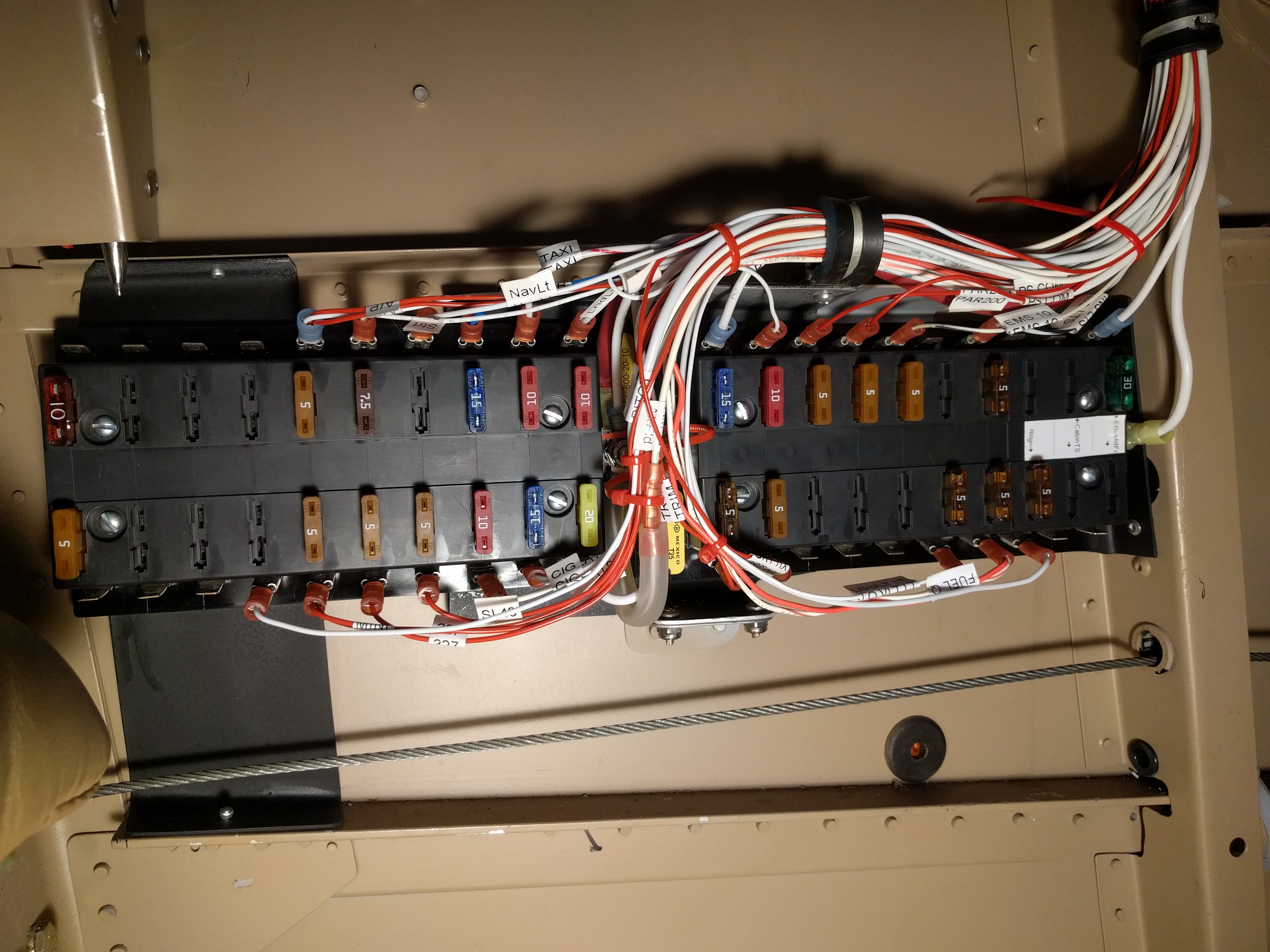
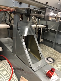
Since you guys have bullied me into using fuses:) , I'm looking at installation

ideas.   I actually see some other benefits other than those mentioned.

The RV14 has an area in the fwd area of the center tunnel that most builders

use.   Vans even has a kit that fits this area to allow the fuse/cb panel to

be angled so it is more accessible and easier to view.   Also gives more space

behind the fuse/cb panel for wiring.


I will attempt to post a couple of pictures to show what I'm considering.

Also, I attached a link to a fuse block I found during initial research.

Sorry, pictures look like they are very large.  I will try and re-size when I

a minute.     T

As always, all critiques and ideas welcome.
| | - The Matronics AeroElectric-List Email Forum - | | | Use the List Feature Navigator to browse the many List utilities available such as the Email Subscriptions page, Archive Search & Download, 7-Day Browse, Chat, FAQ, Photoshare, and much more:
http://www.matronics.com/Navigator?AeroElectric-List |
|
| Description: |
|
| Filesize: |
34.84 KB |
| Viewed: |
26688 Time(s) |
|
| Description: |
|
| Filesize: |
35.99 KB |
| Viewed: |
26688 Time(s) |
|
| Description: |
|
Download |
| Filename: |
BUS_Tns_15710-1880697.pdf |
| Filesize: |
178.25 KB |
| Downloaded: |
790 Time(s) |
|
|
| Back to top |
|
|
|
|
You cannot post new topics in this forum
You cannot reply to topics in this forum
You cannot edit your posts in this forum
You cannot delete your posts in this forum
You cannot vote in polls in this forum
You cannot attach files in this forum
You can download files in this forum
|
Powered by phpBB © 2001, 2005 phpBB Group
|

