 |
Matronics Email Lists
Web Forum Interface to the Matronics Email Lists
|
| View previous topic :: View next topic |
| Author |
Message |
MauleDriver(at)nc.rr.com
Guest
|
 Posted: Wed Dec 10, 2008 9:34 am Post subject: Crimping of machined D-sub pins with 4-Way Indent Pin Cri Posted: Wed Dec 10, 2008 9:34 am Post subject: Crimping of machined D-sub pins with 4-Way Indent Pin Cri |
 |
|
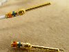
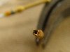
I think I have several problems and oversights that need to be addressed.
I'm using a tool that looks like this:
http://aeroelectric.com/Pictures/Tools/Crimp_Tools/rct-3.jpg
As you said, it is setup for one size of wire and one type of
pin/socket. I've been using it on 20AWG and probably 22 AWG which
would immediately indicate some inconsistency. But in this case, I was
using it on 24AWG wires that was part of a pre-made harness pig tail.
In addition, I was trying to strip the wire just far enough to barely
clear or be flush with the pin. Given that this crimper seems to crimp
concentrically at the the very tip of the pin, allowing any of the
insulation into the pin could further compromise the crimp. (I'm
attaching 2 pics of the pin that failed).
I first need to determine what size wire the crimper is setup for and
limit its use to that wire. And re-confirm I'm using the right pins
(non-high density).
For this particular connection involving the 24AWG wires, I'm going to
follow your guidance on using a 9 pin D-sum with solder terminals along
with shrink tubing, clear adhesive and more shrink tubing. It's a good
solution for this particular connection.
I'll have to take a closer look at the adjustable Daniels crimper if I
want to get serious... but it may be too expensive to justify.
What do you think?
Robert L. Nuckolls, III wrote:
| Quote: |
<nuckolls.bob(at)aeroelectric.com>
At 08:04 AM 12/10/2008, you wrote:
>
> <MauleDriver(at)nc.rr.com>
>
> I've become a bit concerned about the integrity of my crimped D-sub
> pins and socket. I've been giving each connection a tug after
> crimping and I just had one come off. Upon examination, I can't see
> the difference between that connection and others I recently made.
>
> So the question is, what is the proper technique for crimping on
> Machined D-sub pins with a 4-way indent pin crimper? I've searched
> Bob's site and the Web in general and can't find any how-to
> information. None came with the tool I obtained from Stein.
>
> In particular, how should the tool be adjusted? How far should the
> wire be stripped (should the insulation be clear of the pin or should
> it be in the pin)?
Insulation can touch the pin but the wires need to be
inserted a minimum depth as observed through the inspection
hole. My installations have a pretty good gap between
end of pin and insulation when the strands are fully
inserted on the pin.
http://www.aeroelectric.com/Pictures/Connectors/D-Subminature/D-Sub_4-quad-crimp.jpg
If your tool looks like this:
http://aeroelectric.com/Pictures/Tools/Crimp_Tools/rct-3.jpg
There are no adjustments to be made. The tool is set up for
D-sub, 20AWG pins like . . .
http://www.aeroelectric.com/Pictures/Connectors/D-Subminature/D-Sub_20AWG_Pin.jpg
http://www.aeroelectric.com/Pictures/Connectors/D-Subminature/D-Sub_20AWG_Socket.jpg
and should produce a finished joint like the first
picture above.
If your tool looks like this:
http://aeroelectric.com/Pictures/Tools/Crimp_Tools/4-Quad/Daniels_4-Quad_1.jpg
then there are adjustments to be made in addition to selecting
the right pin positioner. The tool should have come with instructions.
http://aeroelectric.com/Pictures/Tools/Crimp_Tools/4-Quad/Daniels_4-Quad_2.JPG
http://aeroelectric.com/Pictures/Tools/Crimp_Tools/4-Quad/Daniels_4-Quad_3.JPG
http://aeroelectric.com/Pictures/Tools/Crimp_Tools/4-Quad/Tool-Locater_Cross_Reference.jpg
> Should I solder?
No . . .
> Avoid the crimp pins altogether and use solder-on D-subs?
Millions of these pins are installed every day world wide and
deliver as advertised. You need to figure out what's going
on with your materials, tools, techniques . . .
> Use the 'regular' crimp on, stamped pins instead?
No, these are more problematic for the neophyte builder than
machined pins. I don't even keep them in the shop. We've
been 100% machined pins for 20+ years.
> Crimp and solder (the hole in the barrel of the pin suggests that may
> be an option).
No, that's an inspection hole. If the wires are sufficiently
inserted you can see the strands through the hole.
> Advice or links are welcome. Thanks
What tool do you have? What pins are you trying to install and
what connector is the target residence for the pins? Are you
trying to install 22AWG (high density) pins with the 20AWG
standard density) tool?
Bob . . .
|
| | - The Matronics AeroElectric-List Email Forum - | | | Use the List Feature Navigator to browse the many List utilities available such as the Email Subscriptions page, Archive Search & Download, 7-Day Browse, Chat, FAQ, Photoshare, and much more:
http://www.matronics.com/Navigator?AeroElectric-List |
|
| Description: |
|
| Filesize: |
79.45 KB |
| Viewed: |
219 Time(s) |
|
| Description: |
|
| Filesize: |
64.55 KB |
| Viewed: |
213 Time(s) |
|
|
|
| Back to top |
|
 |
Bill Schlatterer
Joined: 09 Jan 2006
Posts: 195
|
| Posted: Thu Dec 11, 2008 6:52 pm Post subject: Crimping of machined D-sub pins with 4-Way Indent Pin Cri |
|
|
I used this crimper and D-Subs on my full panel with no problems but it is

not made to do 24 gauge wire.  For that you need to double up the wire and

it will work fine.  Assuming you are using 20-22g wire and pins this tool

works nicely.


One other caution is that with this tool you NEVER double crimp a fitting.

If you partially crimp one and then crimp again, you run the risk of taking

the normal 4 point crimp and making it into an 8 point buzz saw for the

wire.  While you can carefully position a partially crimped terminal in the

jaws and crimp again, it is very likely to cut some or all of the stains in

the wire if not perfectly repositioned.  If you want to try it just crimp a

wire, then rotate it 45 degrees and crimp again.  Most likely, the wire will

easily break right at the terminal.


The trick with this tool is to strip the wire correctly and then hold the

pin in the tool with the wire inserted.  Pressure on the wire keeps the pin

in the right place in the tool. Then make one smooth firm crimp and leave it

alone.


Hope this helps.


Bill S

--
| | - The Matronics AeroElectric-List Email Forum - | | | Use the List Feature Navigator to browse the many List utilities available such as the Email Subscriptions page, Archive Search & Download, 7-Day Browse, Chat, FAQ, Photoshare, and much more:
http://www.matronics.com/Navigator?AeroElectric-List |
|
|
|
| Back to top |
|
|
|
|
You cannot post new topics in this forum
You cannot reply to topics in this forum
You cannot edit your posts in this forum
You cannot delete your posts in this forum
You cannot vote in polls in this forum
You cannot attach files in this forum
You can download files in this forum
|
Powered by phpBB © 2001, 2005 phpBB Group
|

