 |
Matronics Email Lists
Web Forum Interface to the Matronics Email Lists
|
| View previous topic :: View next topic |
| Author |
Message |
dave.saylor.aircrafters(a
Guest
|
 Posted: Thu Mar 29, 2012 2:32 pm Post subject: Uneven dipole elements Posted: Thu Mar 29, 2012 2:32 pm Post subject: Uneven dipole elements |
 |
|
Bob,


We managed to chop about 3 inches off the end of a dipole comm

antenna.  Would that have any appreciable effect on performance?


--Dave Saylor
| | - The Matronics AeroElectric-List Email Forum - | | | Use the List Feature Navigator to browse the many List utilities available such as the Email Subscriptions page, Archive Search & Download, 7-Day Browse, Chat, FAQ, Photoshare, and much more:
http://www.matronics.com/Navigator?AeroElectric-List |
|
|
|
| Back to top |
|
 |
nuckolls.bob(at)aeroelect
Guest
|
| Posted: Thu Mar 29, 2012 6:48 pm Post subject: Uneven dipole elements |
|
|
At 05:30 PM 3/29/2012, you wrote:
| Quote: |
<dave.saylor.aircrafters(at)gmail.com>
Bob,
We managed to chop about 3 inches off the end of a dipole comm
antenna. Would that have any appreciable effect on performance?
|
Sure, but if I were to give you a 'number' . . . it wouldn't
have much practical meaning. Is this an internal antenna?
Can't you splice it back on?
Bob . . .
| | - The Matronics AeroElectric-List Email Forum - | | | Use the List Feature Navigator to browse the many List utilities available such as the Email Subscriptions page, Archive Search & Download, 7-Day Browse, Chat, FAQ, Photoshare, and much more:
http://www.matronics.com/Navigator?AeroElectric-List |
|
|
|
| Back to top |
|
|
dave.saylor.aircrafters(a
Guest
|
| Posted: Thu Mar 29, 2012 9:41 pm Post subject: Uneven dipole elements |
|
|
| Quote: | >Can't you splice it back on?<<
|
Short answer--no.
We had to lop the tip off a vertical stab to make room for more rudder horn on a Lancair ES. I didn't stop to think about an internal antenna. I shoulda.
On further inspection, the antenna seems to have three elements. Two run up each side of the Vstab trailing edge, aft of the stern post. They're embedded in the fiberglass and are nearly equal in length.
The element that was cut off is 8" forward of the Vstab trailing edge. I can't tell exactly how the three segments are connected. The aft-most two elements are visible through the fiberglass when the rudder is removed. I can see a lot of the cut element using a boroscope inside the Vstab.
Would I hurt the radio to try transmitting and receiving? If this isn't easy to fix, we have the option of installing a belly-mounted replacement antenna using a spray-on ground plane.
--Dave Saylor
On Thu, Mar 29, 2012 at 7:45 PM, Robert L. Nuckolls, III <nuckolls.bob(at)aeroelectric.com (nuckolls.bob(at)aeroelectric.com)> wrote:
[quote] --> AeroElectric-List message posted by: "Robert L. Nuckolls, III" <nuckolls.bob(at)aeroelectric.com (nuckolls.bob(at)aeroelectric.com)>
At 05:30 PM 3/29/2012, you wrote:
| Quote: | --> AeroElectric-List message posted by: Dave Saylor <dave.saylor.aircrafters(at)gmail.com (dave.saylor.aircrafters(at)gmail.com)>
Bob,
We managed to chop about 3 inches off the end of a dipole comm
antenna. Â Would that have any appreciable effect on performance?
|
 Sure, but if I were to give you a 'number' . . . it wouldn't
 have much practical meaning. Is this an internal antenna?
 Can't you splice it back on?
 Bob . . .
====================================
-
ric-List" target="_blank">http://www.matronics.com/Navigator?AeroElectric-List
====================================
MS -
k">http://forums.matronics.com
====================================
e -
     -Matt Dralle, List Admin.
t="_blank">http://www.matronics.com/contribution
====================================
[b]
| | - The Matronics AeroElectric-List Email Forum - | | | Use the List Feature Navigator to browse the many List utilities available such as the Email Subscriptions page, Archive Search & Download, 7-Day Browse, Chat, FAQ, Photoshare, and much more:
http://www.matronics.com/Navigator?AeroElectric-List |
|
|
|
| Back to top |
|
|
nuckolls.bob(at)aeroelect
Guest
|
| Posted: Fri Mar 30, 2012 8:11 am Post subject: Uneven dipole elements |
|
|
At 12:39 AM 3/30/2012, you wrote:

 >>Can't you splice it back on?<<


Short answer--no.


We had to lop the tip off a vertical stab to make

room for more rudder horn on a Lancair ES.  I

didn't stop to think about an internal antenna.  I shoulda.


    If the structure needed to be shortened . . . and the

    antenna is embedded in structure, would it have made

    any difference?


On further inspection, the antenna seems to have

three elements.  Two run up each side of the

Vstab trailing edge, aft of the stern

post.  They're embedded in the fiberglass and are nearly equal in length.


    Do you have any documentation on how this antenna was

    installed? I'm having trouble putting my gray-matter

    around your description.


The element that was cut off is 8" forward of the

Vstab trailing edge.  I can't tell exactly how

the three segments are connected.  The aft-most

two elements are visible through the fiberglass

when the rudder is removed.  I can see a lot of

the cut element using a boroscope inside the Vstab.


Would I hurt the radio to try transmitting and

receiving?  If this isn't easy to fix, we have

the option of installing a belly-mounted

replacement antenna using a spray-on ground plane.


    Get an SWR meter and see how bad the crippled antenna

    really is.


    Spray-on ground planes are like using Kleenex for

    wing fabric. Metallic radials on inside of skin

    is both the best and least we know how to do.

   Bob . . .
| | - The Matronics AeroElectric-List Email Forum - | | | Use the List Feature Navigator to browse the many List utilities available such as the Email Subscriptions page, Archive Search & Download, 7-Day Browse, Chat, FAQ, Photoshare, and much more:
http://www.matronics.com/Navigator?AeroElectric-List |
|
|
|
| Back to top |
|
|
wynaire(at)citlink.net
Guest
|
| Posted: Fri Mar 30, 2012 9:46 am Post subject: Uneven dipole elements |
|
|
Bob,

 This ant design sounds like the one I spoke about. BTW:  I found the diagrams and factory instructions, finally. Will scan and send  today. Maybe it will help Dave S. with decision. GL!

 Mike Wynn

 Moab, UT

 **********

 [quote]   ---
| | - The Matronics AeroElectric-List Email Forum - | | | Use the List Feature Navigator to browse the many List utilities available such as the Email Subscriptions page, Archive Search & Download, 7-Day Browse, Chat, FAQ, Photoshare, and much more:
http://www.matronics.com/Navigator?AeroElectric-List |
|
|
|
| Back to top |
|
|
nuckolls.bob(at)aeroelect
Guest
|
| Posted: Fri Mar 30, 2012 10:17 am Post subject: Uneven dipole elements |
|
|
At 12:45 PM 3/30/2012, you wrote:
| Quote: | Bob,
This ant design sounds like the one I spoke about. BTW: I found the diagrams and factory instructions, finally. Will scan and send today. Maybe it will help Dave S. with decision. GL!
Mike Wynn
Moab, UT |
Thank you! I'll post it to the reference documents
folder on the website too.
Bob . . . [quote][b]
| | - The Matronics AeroElectric-List Email Forum - | | | Use the List Feature Navigator to browse the many List utilities available such as the Email Subscriptions page, Archive Search & Download, 7-Day Browse, Chat, FAQ, Photoshare, and much more:
http://www.matronics.com/Navigator?AeroElectric-List |
|
|
|
| Back to top |
|
|
nuckolls.bob(at)aeroelect
Guest
|
| Posted: Fri Mar 30, 2012 10:42 am Post subject: Uneven dipole elements |
|
|
At 01:12 PM 3/30/2012, you wrote:
| Quote: | Thanks! I'd like to know what this antenna looks like.
Off topic: It's on an as-yet unfinished Lancair ES with a 15-year old panel. It had a huge FMS-type display (that won't boot up) called a Avro-Tec FMP 300.
The antenna in question is switched by a Comant gizmo between two comms.
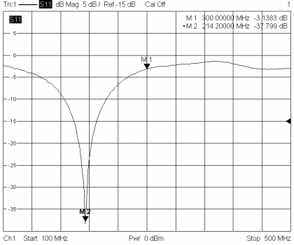
We stumbled back-asswards into an antenna engineer who works for L3 across the street from us. His hobby is helping ham operators build antennas, and he should be here Saturday to do a "sweep"...whatever that is. |
A 'sweep' is done with a supper-whizzy network analyzer
usually fitted the a sweep generator and graphical display
for the output of the analyzer. You get pictures like this
in seconds
[img]cid:.0[/img]
Us poor guys use an SWR meter and variable frequency
energy source to step through the frequencies of
interest and record data. That data is then
massaged like our algebra teachers taught us. After
you've done it a few dozen times, any notions of it
being a 'sweep' are replace the realization that
it's really a 'plod'.
It will be interesting to see what he finds. Take
pictures of his test setup and data to share with
us if you can.
Bob . . .
| | - The Matronics AeroElectric-List Email Forum - | | | Use the List Feature Navigator to browse the many List utilities available such as the Email Subscriptions page, Archive Search & Download, 7-Day Browse, Chat, FAQ, Photoshare, and much more:
http://www.matronics.com/Navigator?AeroElectric-List |
|
| Description: |
|
| Filesize: |
70.61 KB |
| Viewed: |
6075 Time(s) |
|
|
|
| Back to top |
|
|
Float Flyr

Joined: 19 Jul 2006
Posts: 2704
Location: Campbellton, Newfoundland
|
| Posted: Fri Mar 30, 2012 3:48 pm Post subject: Uneven dipole elements |
|
|
I'm wondering if it is now operating like a modified Windom antenna (not

straight at centre and different length elements).  I also would like to

know if it is vertical or horizontal


Noel


--
| | - The Matronics AeroElectric-List Email Forum - | | | Use the List Feature Navigator to browse the many List utilities available such as the Email Subscriptions page, Archive Search & Download, 7-Day Browse, Chat, FAQ, Photoshare, and much more:
http://www.matronics.com/Navigator?AeroElectric-List |
|
_________________
Noel Loveys
Kitfox III-A
Aerocet 1100 Floats |
|
| Back to top |
|
|
nuckolls.bob(at)aeroelect
Guest
|
| Posted: Fri Mar 30, 2012 8:37 pm Post subject: Uneven dipole elements |
|
|
At 06:46 PM 3/30/2012, you wrote:
| Quote: | --> AeroElectric-List message posted by: "Noel Loveys" <noelloveys(at)yahoo.ca>
I'm wondering if it is now operating like a modified Windom antenna (not
straight at centre and different length elements). I also would like to
know if it is vertical or horizontal |
This would be a vertically polarized antenna and
appears to be 1/2 wavelength. Is there enough
'bulk' at the coax end to house a small toroid
transformer?
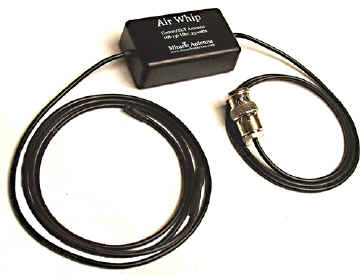
There's another 1/2-wave kid on the block which
is actually a center-fed dipole with the feedline
running up the middle of the lower half of the
dipole. It's marketed as the Air Whip at
http://miracleantenna.com/shop-products/aviation/42
[img]cid:.0[/img]
The black box houses the common-mode choke which
de-couples the feed line from the high-voltage
end of the dipole thusly.
http://tinyurl.com/78ph8nz
http://tinyurl.com/6ul4o6f
Waaayyy back when, there was a brief brush with
tiny toroids to match coax feedlines to center fed
dipoles the cores they used were very low
power handling . . . hence good for receive only.
The Antenna Dynamics product has the look and 'smell'
of a similar product. By the way, the reason it's
not 44" (half wave in free space) long is because
the lower 1/4 wave is in coax which is shortened
to about 14" by the coax velocity factor.
Miracle Antenna is a newer kid on the block
and gets very good reviews from their whole
customer base which includes amateur radio and
SWL applications.
Dave, is there any chance you can get the remnants
of the old antenna out? Putting one of these
in it's place would be a prudent move.
If that's not practical/possible, then splicing an
extension on the upper end to replace the cut off
length would be helpful . . . even if it lays off at
right angles to the antenna. This would serve as
an extension moving back toward 1/4 wave for the
upper element and/or 'capacity' hat to load the
shortened antenna thus making it look electrically
like a quarter wave.
Your antenna guy will know all about this and
will be able to help you with the patch.
Bob . . .
| | - The Matronics AeroElectric-List Email Forum - | | | Use the List Feature Navigator to browse the many List utilities available such as the Email Subscriptions page, Archive Search & Download, 7-Day Browse, Chat, FAQ, Photoshare, and much more:
http://www.matronics.com/Navigator?AeroElectric-List |
|
| Description: |
|
| Filesize: |
41.48 KB |
| Viewed: |
6065 Time(s) |

|
|
|
| Back to top |
|
|
dave.saylor.aircrafters(a
Guest
|
| Posted: Fri Mar 30, 2012 10:35 pm Post subject: Uneven dipole elements |
|
|
We found a diagram of what we think the antenna looks like. I'll post of a picture of it next week at the latest. It's a slanted-N shape similar to an Archer.
Earlier I described equal-length parallel elements. Turns out they're carbon reinforcements that aren't part of the antenna. I'll show them in the picture when I post it.
I mistook them as part of the antenna because I was using a "wire sniffer" to find the elements. I had the transmitter attached to the end we'd cut off, and it was making the carbon strips, which aren't connected to the antenna in any way I can see, display to the receiver wand as conductors.
Thanks to everyone for all the input. We'll get this figured out. I think if I have to I can add a few perpendicular inches to the shortened end.
--Dave Saylor
On Fri, Mar 30, 2012 at 9:36 PM, Robert L. Nuckolls, III <nuckolls.bob(at)aeroelectric.com (nuckolls.bob(at)aeroelectric.com)> wrote:
| Quote: | At 06:46 PM 3/30/2012, you wrote:
| Quote: | --> AeroElectric-List message posted by: "Noel Loveys" <noelloveys(at)yahoo.ca (noelloveys(at)yahoo.ca)>
I'm wondering if it is now operating like a modified Windom antenna (not
straight at centre and different length elements). I also would like to
know if it is vertical or horizontal |
  This would be a vertically polarized antenna and
  appears to be 1/2 wavelength. Is there enough
  'bulk' at the coax end to house a small toroid
  transformer?
  There's another 1/2-wave kid on the block which
  is actually a center-fed dipole with the feedline
  running up the middle of the lower half of the
  dipole. It's marketed as the Air Whip at
 http://miracleantenna.com/shop-products/aviation/42
[img]cid:.0[/img]
   The black box houses the common-mode choke which
   de-couples the feed line from the high-voltage
   end of the dipole thusly.
http://tinyurl.com/78ph8nz
http://tinyurl.com/6ul4o6f
  Waaayyy back when, there was a brief brush with
  tiny toroids to match coax feedlines to center fed
  dipoles the cores they used were very low
  power handling . . . hence good for receive only.
  The Antenna Dynamics product has the look and 'smell'
  of a similar product. By the way, the reason it's
  not 44" (half wave in free space) long is because
  the lower 1/4 wave is in coax which is shortened
  to about 14" by the coax velocity factor.
  Miracle Antenna is a newer kid on the block
  and gets very good reviews from their whole
  customer base which includes amateur radio and
  SWL applications.
  Dave, is there any chance you can get the remnants
  of the old antenna out? Putting one of these
  in it's place would be a prudent move.
  If that's not practical/possible, then splicing an
  extension on the upper end to replace the cut off
  length would be helpful . . . even if it lays off at
  right angles to the antenna. This would serve as
  an extension moving back toward 1/4 wave for the
  upper element and/or 'capacity' hat to load the
  shortened antenna thus making it look electrically
  like a quarter wave.
  Your antenna guy will know all about this and
  will be able to help you with the patch.
 Bob . . .
|
| | - The Matronics AeroElectric-List Email Forum - | | | Use the List Feature Navigator to browse the many List utilities available such as the Email Subscriptions page, Archive Search & Download, 7-Day Browse, Chat, FAQ, Photoshare, and much more:
http://www.matronics.com/Navigator?AeroElectric-List |
|
| Description: |
|
| Filesize: |
41.48 KB |
| Viewed: |
6063 Time(s) |
|
|
|
| Back to top |
|
|
nuckolls.bob(at)aeroelect
Guest
|
| Posted: Sat Mar 31, 2012 11:23 am Post subject: Uneven dipole elements |
|
|
At 01:33 AM 3/31/2012, you wrote:
| Quote: | We found a diagram of what we think the antenna
looks like. I'll post of a picture of it next
week at the latest. It's a slanted-N shape similar to an Archer.
Earlier I described equal-length parallel
elements. Turns out they're carbon
reinforcements that aren't part of the
antenna. I'll show them in the picture when I post it.
|
How much of the structure/skin around this antenna
is carbon? Buried antennas in carbon aircraft typically
don't do real well. Fiberglas/epoxy is okay but the
carbon is both conductive as well as dissipative . . .
in other words it turns a portion of your signal
into heat.
Bob . . .
| | - The Matronics AeroElectric-List Email Forum - | | | Use the List Feature Navigator to browse the many List utilities available such as the Email Subscriptions page, Archive Search & Download, 7-Day Browse, Chat, FAQ, Photoshare, and much more:
http://www.matronics.com/Navigator?AeroElectric-List |
|
|
|
| Back to top |
|
|
|
|
You cannot post new topics in this forum
You cannot reply to topics in this forum
You cannot edit your posts in this forum
You cannot delete your posts in this forum
You cannot vote in polls in this forum
You cannot attach files in this forum
You can download files in this forum
|
Powered by phpBB © 2001, 2005 phpBB Group
|

